Manuals

olympus om 10 manual

Olympus OM-10 Manual: A Comprehensive Guide

This guide details the Olympus OM-10, offering free downloads of its user and repair manuals from sources like the Internet Archive and dedicated libraries․

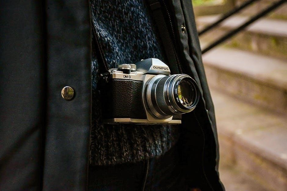
The Olympus OM-10, a cornerstone of 35mm photography, represents a significant step in accessible SLR design․ Released in the 1970s, it brought advanced features to a wider audience․ This camera is celebrated for its compact size, robust build quality, and innovative aperture-priority auto-exposure mode․

Numerous resources, including free downloadable manuals from the Internet Archive, provide comprehensive guidance for both novice and experienced photographers․ These manuals detail every aspect of operation, from basic film loading to advanced techniques․ Olympus’s dedication to medical and optical precision is reflected in the OM-10’s meticulous engineering, ensuring reliable performance and enduring appeal; Explore its legacy!

Historical Context of the OM-10

The Olympus OM-10 emerged during a pivotal era in camera development, the 1970s, when manufacturers strived for compactness and user-friendliness․ Olympus, already renowned for its optical expertise – with a history exceeding a century focused on medical and scientific advancements – aimed to democratize SLR photography․

Prior to the OM series, SLRs were often bulky and intimidating․ The OM-10 challenged this norm with its smaller body and simplified controls, notably the aperture-priority mode․ Resources like freely available manuals document this shift․ Olympus’s commitment to innovation positioned the OM-10 as a popular choice, influencing subsequent camera designs and solidifying its place in photographic history․

Understanding the Olympus OM-10 Features

The OM-10 boasts a compact design and innovative aperture-priority mode, simplifying exposure control for photographers, as detailed in available service manuals․

OM System Overview

Olympus’s OM System, launched in 1972, revolutionized 35mm photography with its focus on compactness and high optical quality․ The OM-10, introduced in 1979, continued this legacy, offering a smaller and more affordable entry point into the system․ This system prioritized a smaller body size without compromising image quality, achieved through a unique half-shutter curtain design․

The OM mount itself is renowned for its excellent lenses, many of which are still highly sought after today․ Olympus focused on creating customer-driven solutions, and the OM series reflects this commitment to innovation and user experience․ The system’s success stemmed from its blend of advanced features and accessibility, making it popular among both amateur and professional photographers․

Key Features of the OM-10

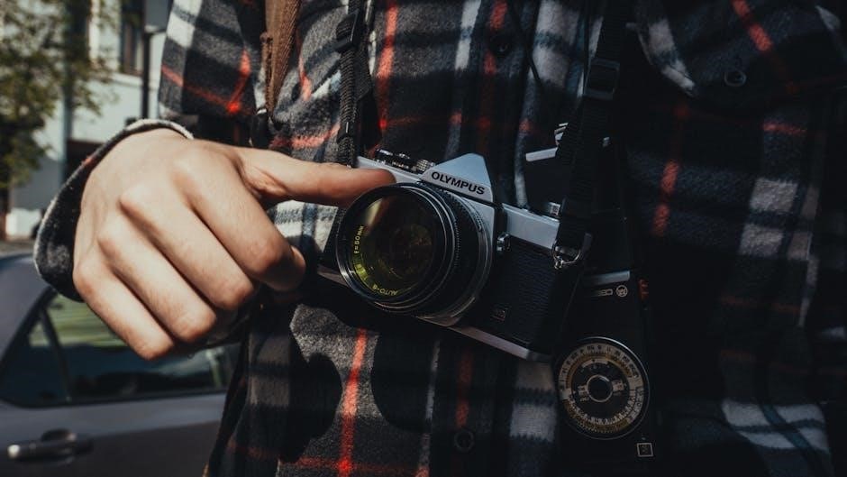
The Olympus OM-10 boasts several defining features․ Primarily, its Aperture Priority mode allows users to select the aperture for depth of field control, while the camera automatically sets the shutter speed․ It features a mechanical shutter with speeds from 1 to 1000th of a second, plus Bulb mode․

A self-timer function is included for delayed shots․ The camera accepts a wide range of Olympus OM mount lenses, known for their sharpness and build quality․ Olympus’s dedication to precision optics is evident․ The OM-10’s compact size and lightweight design enhance portability, making it a practical choice for various photographic situations․

Aperture Priority Mode Explained

Aperture Priority on the Olympus OM-10 is a semi-automatic shooting mode where the photographer controls the lens aperture (f-stop), influencing depth of field․ The camera then automatically selects the appropriate shutter speed for correct exposure․

A wider aperture (lower f-number) creates a shallow depth of field, ideal for isolating subjects, while a narrower aperture (higher f-number) yields greater depth of field, keeping more of the scene in focus․ The OM-10’s metering system assesses the scene’s brightness and sets the shutter speed accordingly, ensuring a properly exposed image․ This mode balances creative control with automation․

Setting Up Your Olympus OM-10

Proper setup involves installing batteries, carefully loading 35mm film, and accurately setting the ISO speed to match your film’s sensitivity․

Battery Installation and Type

The Olympus OM-10 utilizes two SR44 batteries (or equivalent, such as SR43 or Varta 625) to power its light meter․ Accessing the battery compartment requires a small screwdriver to open the battery cover located on the camera’s bottom․ Ensure correct polarity when inserting the batteries – a diagram is usually present inside the compartment․

Incorrect battery installation will prevent the meter from functioning․ Low batteries can lead to inaccurate exposure readings․ Regularly check battery levels, especially during extended use, as the meter’s accuracy is crucial for proper exposure․ Replacing the batteries is a straightforward process, ensuring continued functionality of this classic film camera․

Film Loading Procedure

Loading film into the Olympus OM-10 is a simple process․ First, open the camera back using the film release lever․ Place the film canister into the film chamber on the left side․ Next, pull the film leader across the camera body and insert it into the take-up spool on the right․

Advance the film using the film advance lever until the film leader is securely attached to the take-up spool․ Close the camera back․ The frame counter will automatically begin to advance as you continue to shoot․ Ensure the film is properly loaded to avoid wasted frames and potential damage to the camera or film․

Setting the ISO Speed

Adjusting the ISO setting on the Olympus OM-10 is crucial for correct exposure․ Locate the ISO dial, typically found around the film rewind knob․ Rotate the dial until the desired ISO speed, corresponding to your film’s sensitivity, aligns with the indicator mark․ Common ISO speeds include 100, 200, 400, and 800․

Ensure the selected ISO accurately reflects the film loaded in the camera․ Incorrect ISO settings will result in under or overexposed photographs․ Remember to reset the ISO dial to the correct value each time you change film types for consistent and accurate results․

Using the Olympus OM-10: Shooting Modes

The OM-10 features Aperture Priority and Manual modes, offering creative control over depth of field and shutter speed for diverse photographic scenarios․

Aperture Priority Mode in Detail

Aperture Priority on the Olympus OM-10 allows photographers to select the desired aperture (f-stop), controlling depth of field, while the camera automatically sets the appropriate shutter speed for correct exposure․ This mode excels in situations where depth of field is paramount – landscapes needing everything in focus, or portraits desiring a blurred background․

The camera’s metering system assesses the scene’s brightness and calculates the necessary shutter speed․ However, it’s crucial to monitor the viewfinder’s indicators; if the shutter speed becomes too slow, risking camera shake, or too fast, potentially underexposing the image, utilize exposure compensation to adjust accordingly․ Understanding this interplay between aperture, shutter speed, and the OM-10’s metering is key to mastering this versatile shooting mode․

Manual Mode Operation

Manual mode on the Olympus OM-10 grants complete creative control, requiring the photographer to independently set both the aperture and shutter speed․ This mode is ideal for challenging lighting conditions where the camera’s metering might be inaccurate, or for achieving specific artistic effects․ It demands a solid understanding of the exposure triangle – the relationship between aperture, shutter speed, and ISO․

To operate in manual mode, switch the camera to ‘M’ on the mode dial․ Use the aperture ring on the lens to adjust the lens opening, and the shutter speed dial on the camera body to set the exposure time․ Regularly check the viewfinder’s metering needles to ensure proper exposure, making adjustments as needed for desired results․

Self-Timer Function

The Olympus OM-10 features a convenient self-timer, perfect for self-portraits or situations requiring a delayed shutter release․ Activating the self-timer involves using the dedicated lever located on the left side of the camera body․ Push the lever down and to the right; a light will illuminate, indicating the timer is engaged․

The timer offers two settings: a standard delay and a longer delay․ The standard delay provides approximately 10 seconds, while the longer delay offers around 2 seconds․ Pressing the shutter button initiates the countdown․ The mirror will lock up, and the shutter will release automatically after the selected delay, capturing your image․

Focusing and Exposure

Achieving sharp images with the OM-10 relies on mastering focusing techniques and understanding its metering system for accurate exposure control․

Focusing Techniques with the OM-10

The Olympus OM-10 employs a split-image rangefinder focusing system, renowned for its precision․ Within the viewfinder, a central patch splits when the subject is out of focus; aligning the split halves indicates sharp focus․ This method excels in bright light, offering quick and accurate results․

For low-light situations, or when focusing on subjects lacking strong contrast, microprism collars surrounding the split-image aid in achieving focus․ These collars create a shimmering effect when the subject is slightly out of focus, diminishing as sharpness is attained․ Practice is key to mastering this technique․ Remember to confirm focus before releasing the shutter for consistently crisp images․

Exposure Compensation Explained

The Olympus OM-10’s exposure compensation dial allows manual adjustment of the camera’s metering system, crucial when shooting scenes with unusual lighting․ If the camera underestimates light (e․g․, snow scenes), use positive compensation (+1 or +2) to brighten the image․ Conversely, for scenes the camera overestimates (e․g․, dark subjects), employ negative compensation (-1 or -2) to darken it․

Understanding this dial is vital for accurate exposures․ It overrides the camera’s automatic settings, giving you creative control․ Regularly check your results and adjust accordingly, as correct compensation depends on the specific scene and your desired aesthetic․ Experimentation is encouraged!

Metering System Details

The Olympus OM-10 utilizes a center-weighted metering system, prioritizing light measurement in the central area of the frame․ This means the camera gives more weight to the exposure reading from the center, diminishing towards the edges․ This approach mimics how the human eye perceives light, often yielding natural-looking results․

However, be mindful of strong backlighting or unevenly lit scenes․ The system can be fooled by extreme contrasts․ Utilizing exposure compensation (discussed elsewhere) becomes essential in these situations․ Understanding this weighting is key to mastering the OM-10’s metering and achieving consistently well-exposed photographs․

Advanced Features and Controls

Explore depth of field control, external flash usage, and the unique multiple exposure capabilities the Olympus OM-10 offers for creative photographic expression․

Depth of Field Control

Mastering depth of field is crucial for impactful photography with the Olympus OM-10․ This camera allows precise control through the aperture setting, directly influencing the area of acceptable sharpness in your images․ A wider aperture (smaller f-number like f/2․8) creates a shallow depth of field, ideal for isolating subjects with blurred backgrounds – perfect for portraits․

Conversely, a narrower aperture (larger f-number like f/16) expands the depth of field, keeping more of the scene in focus, suitable for landscapes․ Understanding the relationship between aperture, focal length, and distance to the subject is key․ Experimenting with these settings will unlock creative possibilities, allowing you to guide the viewer’s eye and emphasize specific elements within your photographs․

Using External Flash

The Olympus OM-10 offers a hot shoe for connecting external flash units, expanding your lighting capabilities beyond the built-in options․ Utilizing an external flash provides greater control over light intensity and direction, enabling creative effects and improved image quality in challenging lighting conditions․ Ensure the flash unit is compatible with the OM-10’s hot shoe and supports TTL or manual modes․

When using flash, consider adjusting the aperture to balance the flash output with the ambient light․ Experiment with flash exposure compensation to fine-tune the brightness․ Bounce flash off ceilings or walls for softer, more natural-looking illumination․ Remember to check flash synchronization speed to avoid dark bands in your images․

Multiple Exposure Capability

The Olympus OM-10 allows for multiple exposures, a creative technique where several images are combined onto a single frame of film․ To achieve this, utilize the multiple exposure mode, typically activated by a dedicated lever or setting on the camera body․ After taking the first exposure, re-cock the shutter without advancing the film․

Compose and take the subsequent exposure, layering it over the previous one․ This process can be repeated as desired, building up a complex and artistic image․ Be mindful of overall exposure; multiple exposures can easily become overexposed․ Experiment with different subjects and compositions to unlock unique photographic possibilities․

Troubleshooting Common Issues

Common problems with the OM-10 include exposure and focusing difficulties, and film advance issues; repair manuals offer solutions for these concerns․

Exposure Problems and Solutions

Addressing exposure issues on the Olympus OM-10 often begins with verifying proper battery function, as a weak battery can impact metering accuracy․ Ensure the film speed (ISO) is correctly set, as an incorrect setting directly affects exposure calculations․ If images consistently appear over or underexposed, utilize the exposure compensation feature to fine-tune the meter’s reading․

Check the shutter speeds for accuracy; slow shutter speeds may require a tripod to avoid blur․ Inspect the lens for cleanliness, as dirt or smudges can reduce light transmission․ Consulting the OM-10 repair manual can provide detailed troubleshooting steps for metering system malfunctions, offering schematics and diagnostic procedures for electronics experts․ Remember to test with a fresh roll of film after any adjustments․

Focusing Difficulties

Experiencing focusing issues with your Olympus OM-10? First, ensure proper lighting conditions, as low light can hinder accurate focusing․ Verify the lens is securely mounted and free from any play․ Carefully check the focusing ring for smooth operation; stiffness might indicate internal issues․

When using manual focus, practice utilizing the split-image rangefinder in the viewfinder – align the split images for sharp focus․ If the rangefinder appears dim or misaligned, a professional lens calibration might be necessary․ The OM-10 repair manual offers detailed diagrams for lens disassembly and adjustment, beneficial for experienced technicians․ Remember to double-check focus at different distances․

Film Advance Issues

Encountering problems with film advancing on your Olympus OM-10? Initially, confirm the film is correctly loaded, ensuring it engages with the take-up spool․ A common issue is insufficient tension on the film leader; gently advance and assist its winding․ If the film counter isn’t advancing, or the advance lever feels stiff, inspect for obstructions within the film chamber․

The OM-10 repair manual provides exploded diagrams of the film advance mechanism, aiding in identifying potential component failures․ Check the drive gears for wear or damage․ If self-diagnosis fails, professional servicing is recommended to prevent further damage to the camera’s internal components․

Maintenance and Care

Regular cleaning and proper storage are crucial for the Olympus OM-10’s longevity; lens care and body cleaning maintain optimal performance and appearance․

Cleaning the Camera Body

Maintaining the exterior of your Olympus OM-10 is essential for both its aesthetic appeal and functional integrity․ Begin by using a soft, dry cloth to gently wipe away any dust or fingerprints from the camera body․ For more stubborn smudges, slightly dampen the cloth with a mild lens cleaning solution – avoid harsh chemicals or abrasive cleaners, as these can damage the finish․


Pay particular attention to areas around the film compartment and controls, ensuring no debris accumulates․ A soft brush can be used to dislodge dust from crevices․ Regularly inspect the light seals; if they are deteriorating, consider replacement to prevent light leaks․ Always ensure the camera is turned off and the battery removed before commencing any cleaning procedure․ Careful and consistent cleaning will help preserve your OM-10 for years to come․

Lens Care and Maintenance

Proper lens care is crucial for maintaining optimal image quality with your Olympus OM-10․ Dust and fingerprints on the lens surface can significantly degrade picture sharpness and contrast․ Use a blower to remove loose dust particles before gently wiping the lens with a specialized microfiber lens cloth․

For stubborn smudges, apply a small amount of lens cleaning solution to the cloth, never directly onto the lens․ Avoid excessive pressure during cleaning․ Regularly inspect the lens elements for scratches or fungus; professional cleaning may be required for these issues․ Store lenses with caps on in a dry, dust-free environment to prevent damage and ensure longevity․

Storage Recommendations

Long-term storage of your Olympus OM-10 requires careful consideration to prevent damage․ Ideally, store the camera in a cool, dry place away from direct sunlight and extreme temperatures․ Removing the batteries prevents potential corrosion and battery leakage, which can harm internal components․

A camera bag or case offers protection against dust, impacts, and humidity․ If storing for extended periods, consider using desiccant packs to absorb any residual moisture․ Regularly check the stored camera for signs of mold or corrosion․ Proper storage ensures your OM-10 remains in excellent working condition for years to come․

Olympus OM-10 Repair Information

Repair manuals, schematics, and parts lists for the Olympus OM-10 are available online as PDFs, aiding electronics experts in servicing this camera․

Accessing the Repair Manual

Locating the Olympus OM-10 repair manual is readily achievable through several online resources․ The Internet Archive hosts downloadable PDF versions, offering a convenient way to access detailed schematics and service information․ Dedicated online libraries, such as those specializing in camera documentation, also provide access to these crucial resources․

These manuals, often exceeding 128 pages, contain exploded parts diagrams and comprehensive repair guides․ They are invaluable for electronics experts and experienced technicians undertaking camera maintenance or restoration․ Downloading these files typically requires a simple registration process, ensuring easy access to the necessary documentation for successful repairs․ Remember to check the terms of service for each platform․

Common Repair Needs

Typical repairs for the Olympus OM-10 often involve addressing issues with the film advance mechanism, light sealing foam degradation, and occasional shutter malfunctions․ The camera’s electronic components, while generally reliable, can sometimes require attention, particularly within the metering system․

Access to the detailed repair manual is essential for diagnosing and resolving these problems effectively․ Common needs include replacing worn gears, cleaning the shutter assembly, and restoring the camera’s light seals to prevent unwanted light leaks․ Skilled technicians utilize exploded parts diagrams to identify and replace faulty components, ensuring the OM-10’s continued functionality․

Parts List and Diagrams

The Olympus OM-10 repair manual provides comprehensive parts lists and exploded view diagrams crucial for servicing this classic camera․ These diagrams meticulously illustrate the camera’s internal structure, identifying each component with a specific part number․ This detailed documentation assists technicians in accurately locating and replacing damaged or worn parts․

Access to these resources is invaluable for undertaking repairs, ensuring correct assembly and functionality․ The parts list covers everything from small screws and springs to larger components like the shutter mechanism and focusing screen․ Utilizing these diagrams streamlines the repair process, minimizing errors and maximizing efficiency․

Resources and Further Learning

Explore online manuals, user forums, and communities dedicated to the Olympus OM-10 for expanded knowledge and support regarding this film camera․

Online Manuals and Downloads

Accessing the Olympus OM-10 manual digitally is remarkably straightforward․ The Internet Archive provides a free download option in PDF format, offering both single-page processed JP2 ZIP downloads and TORRENT options for convenient access․

Furthermore, dedicated manual libraries, such as The Manual Library, host the OM-10 user manual, uploaded by contributors like chris85․ These resources offer comprehensive documentation, including detailed parts lists and exploded diagrams, particularly valuable for repair endeavors․

The availability of these online resources ensures that users can readily find information to operate, maintain, and even repair their Olympus OM-10 cameras effectively․

OM-10 User Forums and Communities

Engaging with online communities dedicated to the Olympus OM-10 provides a valuable platform for sharing knowledge and troubleshooting․ While specific forum links aren’t directly provided in the source material, a general search will reveal active user groups and photography enthusiasts passionate about this classic camera․

These forums serve as excellent resources for asking questions, receiving advice on repairs, and discovering unique shooting techniques․

Connecting with fellow OM-10 users fosters a collaborative learning environment, allowing individuals to benefit from collective experience and expertise, enhancing their overall photographic journey with this iconic film camera․

Recommended Accessories

Enhancing the Olympus OM-10 experience involves considering compatible accessories, though the provided text doesn’t detail specifics․ Generally, quality lenses from the OM system are highly recommended to fully utilize the camera’s capabilities․ A light meter, while the OM-10 has one, can be a useful addition for complex lighting situations․

Consider a comfortable camera strap and a protective case for transport․

Exploring external flash units expands creative possibilities, and a lens hood minimizes flare․ Researching and investing in these accessories will elevate your photography with the OM-10․

Manuals

bebird w3-wm user manual

The Bebird W3-WM is a versatile tool gaining traction within the Roblox creator community, particularly for live streaming and content creation. Recent updates, like the Brazil server launch (May 2025), necessitate understanding potential latency impacts.

What is the Bebird W3-WM?

The Bebird W3-WM is a compact, Wi-Fi enabled endoscope designed for detailed visual inspections, now finding innovative applications within the Roblox ecosystem. Creators are utilizing it for unique in-game perspectives and content. Recent Roblox policy changes, including age verification (January 2026) and third-party player restrictions (August 2025), don’t directly impact the device’s functionality, but influence how content is shared.

It allows for real-time image and video transmission, potentially enhancing live streams or recording for Roblox experiences, keeping in mind publishing requirements (December 2025).

Key Features and Benefits

The Bebird W3-WM boasts high-resolution imaging, enabling detailed visuals for Roblox content creation. Its Wi-Fi connectivity facilitates seamless streaming and recording, crucial given Roblox’s evolving experience publishing rules (December 2025). The device’s compact size offers versatility, while potential latency issues with the new Brazil servers (May 2025) should be considered.

Benefits include unique perspectives and enhanced content quality, though Persona age estimation accuracy (November 2025) isn’t directly related.

Unboxing and Component Overview

Initial setup involves verifying package contents and identifying each component, ensuring all parts are present before proceeding with charging and app installation.

Package Contents

Upon opening the Bebird W3-WM package, users should find the primary camera unit itself, designed for versatile inspection tasks. Included are various interchangeable tips for navigating different spaces and accessing tight areas. A flexible extension cable allows for increased reach, crucial for diverse applications. The package also contains a USB-C charging cable for powering the device and a detailed user manual outlining setup and operation. Finally, a small cleaning cloth is provided to maintain optimal lens clarity, ensuring high-quality image transmission during use within platforms like Roblox.

Identifying the Components

The Bebird W3-WM’s core component is the camera head, featuring adjustable LED lights for optimal visibility. The extension cable, crucial for reach, connects securely to the camera. Different tip attachments – hooks, mirrors, and magnets – cater to varied inspection needs. A USB-C port facilitates charging and data transfer. The accompanying app, essential for operation, requires age verification (January 2026) and adherence to Roblox’s chat restrictions. Understanding these components is key for effective use, especially when integrating with Roblox experiences.

Setting Up Your Bebird W3-WM

Initial setup involves charging the device, connecting to a stable Wi-Fi network, and downloading the dedicated app – crucial for utilizing features within Roblox environments.

Charging the Device

Before first use, fully charge your Bebird W3-WM to ensure optimal performance and longevity. Utilize the provided USB cable and a standard 5V/1A power adapter. A full charge typically takes approximately 2-3 hours, indicated by a solid LED light. During charging, the LED may pulse.

Avoid using fast chargers, as they could potentially damage the battery. While charging, the device can still be operated, but performance may be limited. Regularly check the battery level within the app to maintain uninterrupted use during Roblox sessions.

Connecting to Wi-Fi

To utilize the Bebird W3-WM’s full functionality, a stable 2.4GHz Wi-Fi connection is essential for real-time image and video transmission to your device. Open the Bebird app and navigate to the Wi-Fi settings. Select your network and enter the password.

Consider potential latency issues, especially with the new Brazil servers (May 2025). Ensure a strong signal for smooth streaming within Roblox. A weak connection may result in lag or disconnections.

Downloading and Installing the App

The Bebird W3-WM requires a companion app for operation and accessing advanced features. Download the official “Bebird” app from either the Apple App Store (iOS) or Google Play Store (Android). Ensure your device meets the minimum system requirements for optimal performance.

Following installation, grant the app necessary permissions, including camera and microphone access. Be mindful of age verification requirements implemented by Roblox (January 2026) when using the app for in-game content.

Using the Bebird W3-WM

Effectively utilizing the Bebird W3-WM involves understanding its interface and real-time transmission capabilities, crucial for Roblox content creation and streaming experiences.

Powering On/Off

To initiate the Bebird W3-WM, a long press on the power button is required; a subsequent long press will power it down. Ensure sufficient battery charge for optimal performance, especially when utilizing features for Roblox streaming. Considering the Brazil server launch in May 2025, stable power is vital to avoid interruptions. Remember to fully charge before extended use, particularly when integrating with Administer 2.0 for potential Roblox applications, and be mindful of potential software conflicts causing memory dumps (September 2025).

Navigating the Interface

The Bebird W3-WM interface is primarily controlled through the companion mobile application. Familiarize yourself with the app’s layout for adjusting settings like image resolution and camera angle. Given Roblox’s evolving age verification (January 2026) and chat restrictions, ensure smooth operation for live streaming. Remember potential latency issues with the Brazil server launch (May 2025) and consider Administer 2.0 integration for streamlined control, while addressing potential memory dump issues reported in September 2025.

Real-Time Image and Video Transmission

The Bebird W3-WM delivers a live feed to your mobile device via Wi-Fi, crucial for Roblox content creation. Consider potential latency, especially with the new Brazil servers (May 2025). Ensure a stable connection to avoid disruptions during live streams, impacted by Roblox’s age-check rollout (January 2026). Explore Administer 2.0 for potential integration, but be mindful of reported memory dump issues (September 2025) and Roblox’s publishing requirements (December 2025).

Advanced Features and Settings

Explore resolution adjustments, camera angle control, and recording options within the Bebird W3-WM app, vital for Roblox content. Persona age estimation (November 2025) is unrelated.

Adjusting Image Resolution

The Bebird W3-WM app allows users to customize image resolution for optimal streaming or recording quality within Roblox. Higher resolutions demand more bandwidth, potentially impacting performance, especially with the new Brazil servers launching in early 2026. Experiment with settings to balance visual fidelity and stable transmission. Consider lower resolutions if experiencing latency or connection issues, particularly when utilizing third-party Roblox players, which are now under scrutiny (August 2025). Remember that Administer 2.0 testing (October 2024) doesn’t directly affect resolution settings.

Controlling the Camera Angle

The Bebird W3-WM offers precise camera angle control via the companion app, crucial for framing shots within Roblox experiences. Adjustments are essential for effective live streaming, considering Roblox’s evolving age verification and chat restrictions (January 2026). Ensure a clear view, mindful of Persona’s age estimation accuracy (November 2025). Remember, smooth angle transitions enhance viewer engagement. Experiment to find optimal angles, especially when publishing experiences, adhering to the December 2025 requirements.

Recording Video and Taking Photos

The Bebird W3-WM facilitates capturing both video and still images directly through the app, ideal for Roblox content creation. Consider Roblox’s experience publishing requirements (December 2025) when planning recordings. Address potential software conflicts, like the memory dump issue (September 2025), before lengthy sessions. Ensure sufficient storage, and be aware of Administer 2.0’s potential integration for streamlined workflows. High-resolution captures enhance content quality, vital for engaging audiences.

Troubleshooting Common Issues

Common problems include connection difficulties, image quality concerns, and reduced battery life; addressing these ensures smooth operation, especially when streaming to Roblox.

Connection Problems

Experiencing connection issues? First, verify your Wi-Fi network stability, as Roblox’s Brazil server launch (May 2025) might introduce latency. Ensure the Bebird W3-WM is within range of a strong signal. Restart both the device and your router. Check for app updates, as software conflicts—like those addressed in the September 2025 memory dump fix—can disrupt connectivity. Third-party player restrictions (August 2025) shouldn’t directly impact the W3-WM, but confirm Roblox compatibility. Finally, temporarily disable firewalls or VPNs to isolate potential interference.

Image Quality Issues

Poor image quality? Begin by cleaning the camera lens – a simple yet effective solution. Adjust the image resolution within the Bebird W3-WM app settings for optimal clarity. Consider lighting conditions; ensure adequate illumination for a brighter feed. Roblox’s age verification (January 2026) doesn’t affect image transmission, but ensure app permissions are granted. If problems persist, check for software updates addressing potential bugs. Remember, streaming to Roblox requires sufficient bandwidth; latency from the Brazil server (May 2025) could contribute.

Battery Life Concerns

Experiencing short battery life? Reduce screen brightness within the Bebird W3-WM app. Frequent use of high-resolution recording drains power quickly. Ensure the device is fully charged before extended sessions, especially when streaming to Roblox. Background app activity can also impact battery performance. Remember, Roblox’s Administer 2.0 (October 2024) doesn’t directly affect battery usage, but complex integrations might. Consider a portable power bank for longer operation, particularly during Roblox events.

Maintenance and Care

Regular cleaning of the camera lens is crucial for optimal image quality. Store the Bebird W3-WM in a safe, dry place, and check for software updates frequently.

Cleaning the Camera Lens

Maintaining a pristine lens is paramount for clear visuals with your Bebird W3-WM. Gently use a microfiber cloth, specifically designed for optics, to remove dust and fingerprints. Avoid harsh chemicals or abrasive materials, as these can damage the lens coating.

For stubborn smudges, lightly dampen the microfiber cloth with lens cleaning solution – ensure it’s formulated for camera lenses. Always power off the device before cleaning. Regular cleaning, even after minimal use, will significantly enhance your streaming and recording quality within Roblox experiences.

Storing the Device

Proper storage extends the lifespan of your Bebird W3-WM. When not in use, keep the device in a cool, dry place, away from direct sunlight and extreme temperatures. The original packaging offers excellent protection during transport or prolonged storage.

Avoid storing the device with other items that could scratch the lens or damage the components. Regularly check for software updates, as these can improve performance and address potential issues, especially considering Roblox’s evolving platform (December 2025 publishing requirements).


Software Updates

Regular software updates are crucial for optimal Bebird W3-WM performance and compatibility, particularly with evolving platforms like Roblox. Check for updates frequently through the companion app; these address bugs and introduce new features.

Updates can also resolve potential software conflicts, like the memory dump issue reported in September 2025. Keeping your device current ensures seamless integration and avoids issues related to Roblox’s age verification (January 2026) or Administer 2.0 testing.

Safety Precautions

Always operate the Bebird W3-WM within recommended parameters, avoiding environments that could cause damage. Be mindful of Roblox’s evolving policies, like those around third-party players (August 2025).

Operating Environment

Ensure a stable Wi-Fi connection for optimal Bebird W3-WM performance, especially considering potential latency issues with new server launches like the Brazil region (May 2025). Avoid excessively dusty or humid conditions, as these can impact the device’s longevity. Roblox’s age verification rollout (January 2026) doesn’t directly affect the W3-WM, but maintaining a safe online environment is crucial. Remember that Administer 2.0 (October 2024) is a separate tool, unrelated to the W3-WM’s operational needs; Prioritize a well-lit, unobstructed space for clear image transmission.

Avoiding Damage to the Device

Protect your Bebird W3-WM from extreme temperatures and direct sunlight, which can harm internal components. Avoid dropping the device or subjecting it to strong impacts. Be mindful of Roblox’s third-party player restrictions (August 2025) – the W3-WM isn’t a player, but handle it with care. Do not disassemble the device; this voids any warranty. Keep the lens clean, and avoid using abrasive cleaners. Remember Persona’s age estimation (November 2025) is unrelated to physical device care.

Roblox Updates Relevant to Bebird W3-WM Usage (Contextual)

Recent Roblox changes, including age verification (January 2026) and experience publishing requirements (December 2025), may impact live streaming or recording with the Bebird W3-WM.

Age Verification and Chat Restrictions (January 2026)

Roblox’s global rollout of age checks for chat, starting in the U.S. and select regions, could indirectly affect Bebird W3-WM users streaming or recording gameplay. While the device itself isn’t impacted, content creators utilizing in-game chat during broadcasts must ensure compliance with these new requirements.

Creators should be aware that restrictions may limit interaction, potentially altering the viewing experience. Updates on what constitutes “chat” are ongoing, so staying informed is crucial for seamless Bebird W3-WM integration with Roblox content.

Third-Party Roblox Player Restrictions (August 2025)

Roblox is updating its policies to prevent account farming and exploits by restricting the use of the platform within third-party players. While the Bebird W3-WM isn’t a player itself, users employing software that modifies or runs Roblox outside the official client may encounter issues when streaming or recording with the device.

Ensure the Bebird W3-WM is used with a standard, unmodified Roblox installation to avoid potential compatibility problems or policy violations, maintaining a smooth broadcasting experience.

Brazil Server Launch (May 2025) ⸺ Potential Latency Impact

The launch of Roblox servers in São Paulo, Brazil, is exciting for players in the region, but may introduce latency considerations for Bebird W3-WM users streaming or recording. Distance from the new servers could affect real-time image and video transmission quality.

Users should monitor their connection and adjust Bebird W3-WM settings, like resolution, to optimize performance. Testing is recommended to determine the best configuration for a stable broadcast;

Understanding Roblox Payment Methods (Contextual)

Roblox VNG accepts domestic payments, alongside Visa, Mastercard, and JCB (availability varies). This impacts purchases related to Bebird W3-WM integration within Roblox experiences.

Accepted Payment Options

Roblox offers a diverse range of payment methods to accommodate its global user base. Within Vietnam (Roblox VNG), domestic payment options are prioritized, ensuring accessibility for local creators utilizing tools like the Bebird W3-WM for content. Internationally, major credit and debit cards – Visa, Mastercard, and JCB – are widely accepted, contingent on regional availability.

These methods facilitate transactions for in-game purchases, developer subscriptions, and potentially, services related to streaming or recording with the Bebird W3-WM within Roblox experiences.

Administer 2.0 and Testing (Contextual)

Administer 2.0, a Roblox administration tool, presents potential integration avenues for managing live streams or recordings utilizing the Bebird W3-WM within experiences.

Using Administer for Potential Bebird W3-WM Integration

Exploring Administer 2.0’s capabilities reveals possibilities for streamlining Bebird W3-WM-based content creation within Roblox. Creators could potentially utilize Administer’s scripting features to automate tasks related to live stream moderation or recording initiation. This might involve commands to adjust in-game settings optimized for the camera feed. However, direct integration requires custom scripting and understanding of both Administer’s API and the Bebird W3-WM’s functionalities. Remember Administer 1.0 is discontinued, focusing development on the newer version. Thorough testing is crucial to ensure stability and prevent conflicts within the Roblox environment.

Persona Age Estimation (Contextual)

Roblox’s Persona aims for accurate age estimation, crucial with new chat restrictions (January 2026). Concerns exist regarding algorithmic bias and appearance-based discrimination, requiring careful consideration.

Accuracy and Bias Considerations

Roblox acknowledges the importance of Persona’s accuracy, yet admits potential for estimation errors. Questions arose on November 18, 2025, regarding algorithmic fairness and potential biases based on appearance. While striving for impartiality, the system isn’t foolproof. Creators should be aware that estimations aren’t definitive and may require manual review.

Addressing concerns is ongoing, with Roblox committed to refining Persona to minimize inaccuracies and ensure equitable age assessment for all users within the platform’s evolving safety framework.

Roblox Experience Publishing Requirements (December 2025)

Updated publishing rules (December 17, 2025) impact live streaming and recording to Roblox, potentially affecting Bebird W3-WM integration and content distribution workflows.

Impact on Live Streaming/Recording to Roblox

The December 2025 publishing changes necessitate careful consideration for Bebird W3-WM users intending to stream or record gameplay. Creators must now adhere to stricter requirements for public experience releases, potentially impacting workflows. This includes ensuring compliance with age verification protocols (January 2026) and chat restrictions. Furthermore, the introduction of Persona age estimation (November 2025) could influence content visibility. Understanding these updates is crucial for seamless integration and avoiding publishing delays, especially when utilizing external devices like the Bebird W3-WM for content capture.

Memory Dump Issue and Troubleshooting (September 2025)

Addressing potential software conflicts is key when encountering memory dump issues while launching Roblox. Clear communication and detailed reports aid resolution efforts.

Addressing Potential Software Conflicts

Identifying conflicting software is crucial for resolving memory dump issues within Roblox, especially when utilizing external tools like the Bebird W3-WM. Ensure compatibility by temporarily disabling recently installed programs or drivers. Consider potential clashes with anti-virus software or streaming applications; Regularly updating Roblox and your system drivers can mitigate these conflicts. Detailed error reports, including screenshots, are invaluable for pinpointing the source of the problem and seeking community support or Roblox’s assistance.

The Bebird W3-WM offers exciting possibilities for Roblox content creators, but staying informed about platform updates – like age verification (January 2026) – is vital.

Recap of Key Features

The Bebird W3-WM shines as a versatile tool, especially relevant given Roblox’s evolving landscape. Its real-time image and video transmission capabilities are crucial for content creation, aligning with the platform’s increasing focus on immersive experiences. Understanding recent changes, such as the Administer 2.0 testing phase (October 2024) and potential memory dump issues (September 2025), is key. The device’s adaptability, coupled with Roblox’s updates regarding payment methods (VNG accepting Visa/Mastercard) and experience publishing requirements (December 2025), positions it as a valuable asset for creators.

Future Developments

Looking ahead, potential Bebird W3-WM integration with Roblox tools like Administer 2.0 presents exciting possibilities. Addressing software conflicts causing memory dumps (September 2025) will be crucial. Further development should focus on optimizing performance alongside Roblox’s age verification and chat restrictions (January 2026). Considering the impact of Brazil server latency (May 2025) and Persona’s age estimation accuracy (November 2025) will also be vital for a seamless user experience within the evolving Roblox ecosystem.

Manuals

manual for uniden bearcat scanner

Uniden Bearcat Scanner Manual: A Comprehensive Guide

This guide offers detailed instructions for Uniden Bearcat scanners‚ covering models like BC898T‚ BCD396T‚ and BC120XLT‚ alongside Sentinel software installation and operation.

Uniden Bearcat scanners are renowned for their reliability and performance in monitoring various radio frequencies‚ serving enthusiasts‚ professionals‚ and public safety personnel alike. These scanners allow users to listen to police‚ fire‚ emergency medical services‚ and other communication channels.

A comprehensive manual is crucial for unlocking the full potential of your scanner. Understanding the features‚ programming methods‚ and troubleshooting steps ensures optimal operation. Resources like the Uniden support website and online forums provide valuable assistance. Models such as the BC898T‚ BCD396T‚ and BC120XLT each possess unique capabilities‚ detailed in their respective manuals. Proper setup‚ including Sentinel software installation‚ is key to a successful scanning experience.

Understanding Scanner Terminology

Navigating the world of scanners requires familiarity with specific terms. VFOs (Variable Frequency Oscillators) represent manually programmable frequencies‚ while memory channels store pre-defined frequencies for quick access. Conventional systems utilize single frequencies‚ whereas trunked systems employ a more complex network.

Sentinel software is a vital tool for programming and managing scanner data. System information refers to the frequencies and settings for specific communication networks. Understanding these terms‚ alongside concepts like search modes and scan lists‚ is essential for effective scanner operation. A solid grasp of this terminology‚ detailed within the Uniden Bearcat manual‚ enhances the user experience and troubleshooting capabilities.

Uniden Bearcat Scanner Models: An Overview

Uniden Bearcat offers a diverse range of scanners catering to various needs. The BC898T is a popular choice known for its versatility‚ while the BCD396T excels in trunked system decoding. The BC120XLT provides a more compact and user-friendly experience.

Each model boasts unique features and capabilities‚ detailed within its respective manual. These scanners can simultaneously scan both conventional and trunked systems (BCD396T). Accessing detailed specifications‚ programming instructions‚ and troubleshooting tips for each model is crucial for optimal performance. Understanding these differences allows users to select the scanner best suited for their specific monitoring requirements.

BC898T Model Specifics

The Uniden Bearcat BC898T is a highly regarded scanner‚ featuring 800 channels and capable of scanning across multiple bands. Its manual details comprehensive programming options‚ including manual entry and utilizing Sentinel software for streamlined setup. This model supports both conventional and trunked systems‚ offering broad coverage for various communications.

Users can access detailed information on VFOs (Variable Frequency Oscillators) and memory channels within the 64-page manual. It provides guidance on search modes and scan lists for customized monitoring. Troubleshooting sections address common issues‚ ensuring users can resolve problems efficiently. The BC898T’s versatility makes it a favorite among enthusiasts.

BCD396T Model Specifics

The BCD396T stands out with its ability to simultaneously scan both conventional and trunked systems‚ a feature highlighted in its manual. This scanner boasts extensive channel capacity and supports a wide range of frequencies‚ making it ideal for diverse monitoring needs. The manual provides detailed instructions for programming via manual entry or the Sentinel software‚ simplifying the setup process.

Users will find comprehensive guidance on utilizing advanced features like search modes and customizable scan lists. Troubleshooting sections address potential issues‚ ensuring optimal performance. The BCD396T’s manual is a valuable resource for maximizing its capabilities and understanding its complex functionalities‚ catering to both novice and experienced users.

BC120XLT Model Specifics

The BC120XLT manual provides a user-friendly guide to operating this popular scanner model. It details the process of setting up and programming the scanner for both conventional and trunked systems‚ offering clear instructions for manual entry of frequencies. The manual emphasizes the scanner’s versatility and ease of use‚ making it accessible to beginners.

Users can expect to find detailed explanations of VFOs and memory channels‚ alongside troubleshooting tips for common issues like programming errors. The BC120XLT manual serves as a crucial resource for understanding the scanner’s features and maximizing its performance‚ ensuring a satisfying scanning experience for all users.

Initial Setup and Powering On

Before first use‚ carefully unpack your Uniden Bearcat scanner and inspect for any damage. Connect the appropriate power source – either the included AC adapter or batteries‚ ensuring correct polarity; The manual stresses the importance of proper power connection for optimal performance and to avoid potential issues.

Upon powering on‚ the scanner will initiate a self-test. Familiarize yourself with the display panel and key functions as outlined in the manual. Initial setup may involve setting the clock and date‚ and selecting your desired operating mode. Following these steps ensures a smooth start to your scanning experience.

Installing Sentinel Software

Sentinel software is crucial for advanced programming and system management of your Uniden Bearcat scanner. Before installation‚ ensure your computer meets the minimum system requirements detailed in the scanner’s manual. Download the correct version of Sentinel‚ compatible with your specific scanner model – BC898T‚ BCD396T‚ or BC120XLT – from the Uniden support website or a trusted source.

The installation process is straightforward‚ typically involving running the downloaded executable file and following the on-screen prompts. Pay close attention to any security warnings and grant necessary permissions. Successful installation enables you to download system information and upload it directly to your scanner‚ streamlining the programming process.

Downloading Sentinel Software

Acquiring the Sentinel software is a vital step in unlocking the full potential of your Uniden Bearcat scanner. The primary source for downloading Sentinel is the official Uniden Support Website. Ensure you select the version specifically designed for your scanner model – whether it’s the BC898T‚ BCD396T‚ or BC120XLT – to guarantee compatibility and optimal performance.

Alternatively‚ some online forums and communities dedicated to scanner enthusiasts may offer download links. However‚ exercise caution when downloading from unofficial sources to avoid potential malware or corrupted files. Always verify the file’s integrity before installation. A direct download link was noted as available as of February 7‚ 2024.

Sentinel Software Installation Process

Once downloaded‚ the Sentinel software installation is generally straightforward. Begin by double-clicking the downloaded file to launch the setup wizard. Follow the on-screen prompts‚ carefully reading each step. You’ll likely be asked to accept a license agreement and choose an installation directory – the default location is usually sufficient.

During installation‚ the software may request necessary drivers for communication with your Uniden Bearcat scanner. Ensure your scanner is not connected to your computer during the initial software installation phase. Connect it after the software is fully installed‚ as prompted by the program. A successful installation will prepare you for programming your scanner.

Programming Methods: Manual Entry

Manual programming involves directly inputting frequencies and settings into your Uniden Bearcat scanner using the keypad and menu system. This method‚ while time-consuming‚ offers precise control and is useful when system information isn’t readily available digitally. Consult your scanner’s specific model manual for detailed instructions on navigating the menu structure.

Carefully enter each frequency‚ offset (if applicable)‚ and any associated settings like tone frequencies or system types. Double-check your entries to avoid errors. Manual entry requires patience and accuracy‚ but it’s a valuable skill for scanner enthusiasts. Remember to save your work frequently to prevent data loss.

Programming Methods: Using Sentinel Software

Sentinel software significantly simplifies programming your Uniden Bearcat scanner. Download and install the correct version for your model – crucial for compatibility. This software allows you to download system information from online databases or create custom systems. You can then upload this data directly to your scanner via a programming cable.

The software interface provides a user-friendly way to manage frequencies‚ channels‚ and settings. Editing and organizing your scanner’s configuration becomes much easier than manual entry. Regularly back up your scanner’s data using Sentinel to safeguard against accidental loss or corruption.

Connecting the Scanner to Your Computer

Establishing a connection between your Uniden Bearcat scanner and your computer is essential for programming and data transfer using Sentinel software. Typically‚ this requires a specific programming cable‚ often a USB cable‚ compatible with your scanner model. Ensure the cable is securely connected to both the scanner and a USB port on your computer.

Driver installation might be necessary for the computer to recognize the scanner. Sentinel software usually guides you through this process. Once connected‚ the software will establish communication‚ allowing you to download system information or upload programmed data. Verify the connection within the Sentinel software before proceeding.

Downloading System Information

System information download is a crucial step in programming your Uniden Bearcat scanner‚ enabling it to receive and decode signals from local public safety‚ emergency services‚ and other radio communications. Using Sentinel software‚ you can access online databases containing frequency lists and system details for your region.

The process involves selecting your location within the software and initiating a download. This data includes frequencies‚ talkgroups‚ and system types. Regularly updating this information ensures your scanner remains current with any changes in local radio systems. Accurate system data is vital for optimal scanning performance and reception.

Uploading System Information to the Scanner

Once downloaded‚ the system information must be uploaded to your Uniden Bearcat scanner via a USB connection and Sentinel software. This transfers the frequencies‚ talkgroups‚ and system configurations from your computer to the scanner’s memory. Ensure a stable connection during the upload process to prevent errors or data corruption.

The software guides you through the upload‚ typically offering options to overwrite existing data or add new systems. Carefully review these options before proceeding. Successful upload allows the scanner to recognize and decode signals from the programmed systems‚ enabling effective monitoring of desired radio communications. Regular uploads keep your scanner updated.

Scanning Conventional Systems

Conventional systems utilize a single frequency for communication‚ making them straightforward to scan. Program these frequencies into your Uniden Bearcat scanner using manual entry or Sentinel software. Ensure correct frequency input‚ including any necessary offsets or PL tones for clear reception. The scanner sequentially checks each programmed frequency for activity.

For optimal performance‚ prioritize frequently used frequencies and consider scan lists to focus on specific channels. Understanding frequency allocations in your area is crucial for effective conventional scanning. These systems are commonly used by public safety‚ fire departments‚ and various businesses for direct communication.


Scanning Trunked Systems

Trunked systems‚ unlike conventional ones‚ dynamically allocate frequencies to groups‚ requiring a different scanning approach. Your Uniden Bearcat scanner‚ particularly models like the BCD396T‚ can handle these complex systems. Downloading system information via Sentinel software is essential for proper operation; this data contains the necessary control channel and talkgroup details.

The scanner monitors the control channel to learn which frequencies are currently in use by specific talkgroups. Proper configuration ensures you hear communications relevant to your interests. Trunked systems are frequently employed by larger public safety agencies for efficient radio resource management.

Troubleshooting Common Issues

Encountering problems with your Uniden Bearcat scanner is common. If the scanner fails to power on‚ verify the power source and battery condition. Programming errors can occur during manual entry or software uploads; double-check your settings and consider re-downloading system information.

Poor reception often stems from antenna placement or interference; Experiment with antenna location and ensure it’s properly connected. Regularly check the Uniden support website and online forums for solutions to frequently reported issues. Remember to consult the manual for specific error codes and their meanings.

Scanner Not Powering On

If your Uniden Bearcat scanner won’t power on‚ begin with the basics. Ensure the power adapter is securely connected to both the scanner and a working electrical outlet. If using batteries‚ verify they are correctly installed and fully charged‚ or try a fresh set. Inspect the battery contacts for corrosion or damage.

A completely dead scanner might require a reset. Consult your specific model’s manual for reset procedures. If the problem persists‚ check the fuse (if applicable) and consider contacting Uniden support for further assistance. Remember to always disconnect the power source before inspecting internal components.

Programming Errors

Encountering programming errors with your Uniden Bearcat scanner often stems from incorrect data entry or corrupted system files. When manually programming‚ double-check all frequencies‚ offsets‚ and tones for accuracy. Utilizing Sentinel software can minimize these errors‚ but ensure the software is correctly installed and updated.

If errors occur during uploads‚ verify the system information file is compatible with your scanner model. Corrupted files can cause programming failures. Try re-downloading the system file or performing a factory reset on the scanner (refer to your manual for instructions) before attempting to reprogram.

Poor Reception

Experiencing poor reception with your Uniden Bearcat scanner can be frustrating. First‚ ensure the antenna is properly connected and of good quality; a better antenna significantly improves signal strength. Location matters – try moving the scanner to a higher elevation or closer to a window.

Interference from electronic devices or physical obstructions like buildings can also weaken signals. Experiment with antenna placement to minimize interference. Check for active frequencies in your area and confirm your scanner is programmed to receive them. Finally‚ consider the distance to the transmission source; signals weaken over distance.

Understanding VFOs and Memory Channels

VFOs (Variable Frequency Oscillators) allow direct frequency input for immediate listening‚ offering flexibility for exploring signals. However‚ frequencies entered into VFOs are lost when the scanner powers off. Memory channels‚ conversely‚ store frequencies permanently‚ even without power‚ creating a customized listening experience.

Utilizing both is key; Scan frequently used frequencies by saving them to memory channels for quick access. Use VFOs for temporary monitoring or discovering new signals. Properly managing VFOs and memory channels maximizes your scanner’s potential and simplifies operation‚ ensuring you don’t lose important frequencies.

Advanced Features: Search Modes and Scan Lists

Uniden Bearcat scanners offer powerful search modes to automatically locate active signals within specified frequency ranges. These modes efficiently scan for transmissions‚ identifying potential channels of interest. Scan lists provide customized groupings of frequencies or memory channels‚ allowing focused monitoring of specific systems or services.

Mastering these features enhances scanning efficiency. Utilize search modes to discover new activity‚ then save discovered frequencies to dedicated scan lists. This targeted approach minimizes irrelevant signals and prioritizes desired communications. Experiment with different search parameters and scan list configurations to optimize performance for your specific listening needs.

Resources and Support

For comprehensive assistance with your Uniden Bearcat scanner‚ the Uniden Support Website is an invaluable resource‚ offering downloadable manuals‚ FAQs‚ and troubleshooting guides. Beyond the official site‚ a vibrant community thrives in online forums and communities dedicated to scanner enthusiasts.

These forums provide a platform to exchange knowledge‚ seek advice from experienced users‚ and find solutions to common issues. Sharing experiences and collaborating with fellow scanner operators can significantly enhance your understanding and enjoyment of your scanner. Remember to consult these resources when encountering difficulties or seeking to expand your scanning expertise.

Uniden Support Website

The official Uniden Support Website serves as a primary hub for all your scanner-related needs. Here‚ you can directly access and download manuals for various Uniden Bearcat models‚ including the BC898T‚ BCD396T‚ and BC120XLT. These manuals provide detailed instructions on operation‚ programming‚ and troubleshooting.

Furthermore‚ the website features a comprehensive FAQ section addressing common user queries and a dedicated troubleshooting area to help resolve technical issues. Utilizing these resources ensures you have the necessary information to maximize your scanner’s functionality and address any challenges encountered during operation. It’s a vital starting point for support.

Online Forums and Communities

Numerous online forums and communities are dedicated to Uniden Bearcat scanners‚ offering a wealth of user-generated knowledge and support. These platforms provide a space to connect with fellow enthusiasts‚ share programming tips‚ and troubleshoot complex issues collaboratively.

Experienced users frequently post solutions to common problems‚ share custom system information downloads‚ and offer guidance on advanced features. Participating in these communities can significantly enhance your understanding of scanner operation and programming‚ supplementing the official manual; They are invaluable resources for finding answers and expanding your scanning expertise beyond the provided documentation.

Manuals

wtw5057lw0 manual

WTW5057LW0 Manual: Comprehensive Guide

This detailed manual provides comprehensive instructions for the WTW5057LW0 washer, covering installation, operation, maintenance, and troubleshooting, alongside repair guidance.

Welcome to the comprehensive guide for your WTW5057LW0 washing machine! This manual is designed to provide you with all the necessary information to ensure optimal performance and longevity of your appliance. Before operating, carefully review the safety precautions detailed within this document to prevent potential hazards and ensure safe usage. Understanding your washer’s features and capabilities will maximize its efficiency and effectiveness in cleaning your laundry.

This guide covers everything from initial setup and daily operation to advanced troubleshooting and maintenance procedures. We’ll explore the washer’s components, control panel functions, and various wash cycles available. Furthermore, we will delve into resolving common issues and locating replacement parts when needed. Remember to retain this manual for future reference and assistance.

Safety Precautions and Warnings

To ensure your safety and prevent damage to the WTW5057LW0 washer, please adhere to the following precautions; Always disconnect the power supply before performing any maintenance or repairs. Never attempt to repair the appliance yourself if you are not qualified; contact a certified technician. Keep children and pets away from the washer during operation. Do not overload the washer, as this can cause damage and affect performance.

Avoid using flammable liquids or harsh chemicals near the appliance. Ensure proper grounding to prevent electrical shock. Regularly inspect the power cord for damage and replace if necessary. Do not operate the washer with a damaged cord or plug. Be cautious of hot water and steam during and after cycles. Always follow detergent manufacturer’s instructions. Ignoring these warnings may void your warranty.

Understanding the Washer’s Components

This section details the internal and external parts of the WTW5057LW0 washer, explaining their functions and how they contribute to optimal cleaning performance.

Washer Control Panel Overview

The WTW5057LW0 washer’s control panel is designed for intuitive operation, offering a range of wash cycles and customizable settings. The panel typically features a digital display indicating cycle status and remaining time. Key buttons include ‘Start/Pause’, allowing convenient control over the wash process.

Cycle selection options generally encompass Normal, Delicates, Heavy Duty, Quick Wash, and Bulky Items, catering to diverse laundry needs. Temperature settings – Hot, Warm, and Cold – are readily adjustable. Additional features, such as spin speed control and soil level selection, provide further customization.

Dedicated buttons may activate options like ‘Extra Rinse’ or ‘Pre-Soak’. Understanding each button’s function is crucial for maximizing the washer’s capabilities and achieving optimal cleaning results. Refer to the detailed cycle guide within this manual for specific recommendations based on fabric type and soil level.

Internal Parts and Their Functions

The WTW5057LW0 washer’s internal components work in harmony to deliver effective cleaning. The motor drives the agitator or impeller, creating the washing action. A water inlet valve controls water flow into the tub, regulated by temperature settings. The pump efficiently drains water after each wash and rinse cycle.

A crucial component is the transmission, linking the motor to the agitator, ensuring proper movement. The tub itself, constructed from durable materials, holds the laundry during the wash process. The lid lock mechanism enhances safety by preventing operation while the lid is open.

Sensors monitor water levels and temperature, providing feedback to the control board. The control board acts as the ‘brain’, coordinating all functions. Understanding these parts aids in troubleshooting and potential repairs, ensuring the longevity of your WTW5057LW0 washer.

Drum and Agitator Details

The WTW5057LW0 washer features a durable stainless steel drum designed to withstand repeated use and provide efficient cleaning. The agitator, centrally located within the drum, creates water movement to thoroughly wash clothes. Its fin design enhances scrubbing action, removing dirt and stains effectively. Different wash cycles utilize varying agitator speeds and patterns.

The drum’s perforations allow water circulation while retaining laundry items. Regular inspection of the agitator is crucial; ensure it’s securely attached and free from obstructions. Damage to the agitator can lead to inefficient washing or unusual noises.

Proper loading of the drum, avoiding overloading, is essential for optimal performance. Understanding the drum and agitator’s functions contributes to maximizing the washer’s cleaning capabilities and extending its lifespan.

Installation and Setup

Proper installation ensures optimal performance and longevity of your WTW5057LW0 washer. Carefully follow these steps for water, electrical connections, and leveling.

Unpacking and Initial Inspection

Upon delivery, carefully inspect the WTW5057LW0 washer for any visible signs of damage incurred during transit. Before unpacking, note the model and serial number for future reference and warranty claims;

Remove all packaging materials, including cardboard, foam inserts, plastic wrap, and shipping bolts. These bolts must be removed from the rear of the washer before operation to prevent damage during the wash cycle.

Retain the packaging materials for a short period, in case a return or exchange is necessary. Check for all included accessories, such as the drain hose, inlet hoses, and any documentation. If any parts are missing or damaged, immediately contact the retailer or manufacturer’s customer support.

Ensure the washer is placed on a level and stable surface before proceeding with the installation.

Water Supply Connection

Connect the inlet hoses to both the washer and the hot and cold water supply faucets. Ensure a tight, leak-proof connection using appropriate pliers, but avoid over-tightening. Use new hoses for initial installation; do not reuse old ones.

The WTW5057LW0 requires standard household water pressure. If water pressure is excessively high, install a pressure regulator to prevent damage to the washer’s internal components. Check for kinks or obstructions in the hoses.

Before fully opening the faucets, briefly turn them on and off to flush out any debris that may be present in the water lines. This prevents sediment from entering and potentially damaging the washer’s valves.

Regularly inspect the hoses for cracks, bulges, or leaks, and replace them as needed to maintain optimal performance and prevent water damage.

Electrical Requirements and Grounding

The WTW5057LW0 washer operates on a standard 120-volt, 60Hz electrical supply. A dedicated, properly grounded three-prong electrical outlet is essential for safe operation. Do not use extension cords or adapters, as they can pose a safety hazard and may not provide sufficient power.

Ensure the circuit breaker for the washer’s outlet is appropriately sized – typically 15 or 20 amps. Never attempt to modify the power cord or plug. If the outlet is not compatible, consult a qualified electrician to install a suitable one.

Proper grounding is crucial to prevent electrical shock. The washer’s grounding wire must be securely connected to a properly grounded electrical system. Regularly inspect the power cord for damage and replace it if necessary.

Always disconnect the washer from the power supply before performing any maintenance or repairs.

Leveling the Washer

Proper leveling is vital to minimize vibration and noise during operation of the WTW5057LW0 washer. Use a spirit level to check the washer’s stability on the floor. Adjustable leveling legs are located at each corner of the washer’s base.

Rotate the legs clockwise to lower that corner and counterclockwise to raise it. Continue adjusting until the washer is perfectly level in both directions – front-to-back and side-to-side.

Once leveled, tighten the lock nuts against the washer’s base to secure the legs in place. This prevents accidental movement and maintains the level during wash cycles.

Re-check the leveling periodically, especially after moving the washer. An uneven washer can cause excessive wear and tear and potentially damage the floor.


Operating Instructions

Effectively utilize the WTW5057LW0 washer by carefully loading laundry, selecting appropriate wash cycles, and understanding detergent dispenser guidelines for optimal cleaning.

Loading and Unloading Laundry

Properly loading your WTW5057LW0 washer is crucial for effective cleaning and preventing damage. Distribute items loosely within the drum, avoiding overcrowding to allow sufficient space for agitation.

Separate laundry by fabric type, color, and soil level before loading. Check pockets for any objects that could cause damage or clog the drain pump.

For optimal results, do not exceed the maximum load capacity specified in the washer’s specifications. Overloading can reduce cleaning performance and strain the motor.

When unloading, carefully remove items from the drum, checking for any remaining small objects. Ensure the drum is completely empty before closing the lid.

Delicate items should be placed in a mesh laundry bag for added protection during the wash cycle.

Detergent Dispenser Guide

The WTW5057LW0 washer features a multi-compartment detergent dispenser designed for optimal detergent usage. Locate the dispenser drawer, typically situated on the top left of the washer.

The dispenser is divided into sections for pre-wash detergent, main wash detergent, fabric softener, and bleach. Always refer to the detergent packaging for recommended dosage amounts based on load size and soil level.

Pour liquid detergents directly into the designated compartments, avoiding overfilling. For powdered detergents, ensure they dissolve completely.

Never pour detergent directly into the wash drum, as this can lead to residue buildup and reduced cleaning performance.

Regularly clean the detergent dispenser to prevent clogs and ensure proper dispensing.

Wash Cycle Selection

The WTW5057LW0 washer offers a variety of wash cycles to accommodate different fabric types and cleaning needs. Familiarize yourself with each cycle for optimal results.

Common cycles include Normal/Regular for everyday laundry, Delicate for fragile items, Heavy Duty for heavily soiled loads, and Quick Wash for lightly soiled items needing a fast refresh.

Additional cycles may include Bulky Items, Whites, Colors, and Rinse & Spin. Carefully consider the fabric type and soil level when selecting a cycle.

Adjust water temperature and spin speed according to the garment care label. Hot water is ideal for whites and heavily soiled items, while cold water is best for delicates and colors.

Refer to the complete cycle guide within this manual for detailed descriptions and recommended settings.

Using Special Features (e.g., Bulky Items, Quick Wash)

The WTW5057LW0 washer incorporates several special features designed to enhance cleaning performance and convenience. The Bulky Items cycle utilizes a slower agitation speed and extended wash times, ideal for comforters and blankets.

The Quick Wash cycle provides a faster cleaning option for lightly soiled loads, reducing wash time significantly. Utilize the Deep Clean option for heavily stained garments, employing increased agitation and water temperature.

A Sanitize cycle offers enhanced cleaning, eliminating bacteria and allergens. Explore the Extra Rinse option to ensure thorough detergent removal, beneficial for sensitive skin.

Remember to adjust load size appropriately when using special features. Overloading can diminish effectiveness. Consult the full feature guide within this manual for detailed instructions and optimal settings.

Maintenance and Troubleshooting

Regular cleaning, filter maintenance, and addressing error codes are crucial for optimal washer performance and longevity. This section details solutions.

Cleaning the Washer

Maintaining a clean washer is essential for optimal performance and preventing unpleasant odors. Regularly wipe down the exterior surfaces with a damp cloth and mild detergent.

For the interior, run a cleaning cycle monthly using a washer cleaner specifically designed for your WTW5057LW0 model. Alternatively, you can use a cup of white vinegar added to the detergent dispenser and run a hot water cycle.

Pay close attention to the detergent dispenser, removing any residue buildup. Inspect the rubber door seal for mold or mildew and clean it thoroughly with a bleach solution (diluted appropriately).

Don’t forget to wipe down the inside of the drum after each use to prevent lingering moisture. A clean washer ensures cleaner clothes and extends the appliance’s lifespan.

Filter Cleaning Procedures

The WTW5057LW0 washer features a filter designed to catch lint, debris, and small objects, preventing drain blockages. Locate the filter access panel, typically at the front bottom of the machine.

Before opening, place towels around the area to absorb any spilled water. Carefully unscrew the filter cap, as water may be present. Remove the filter and thoroughly clean it under running water, removing all accumulated lint and debris.

Inspect the filter housing for any obstructions and clear them out. Reinstall the cleaned filter, ensuring it’s securely tightened. Regularly cleaning the filter – at least every six months – maintains optimal drainage and prevents potential issues.

A clogged filter can lead to reduced washing performance and error codes.

Common Error Codes and Solutions

The WTW5057LW0 washer utilizes error codes to indicate malfunctions. An “F01” code often signals a water inlet issue – check the water supply hoses for kinks or obstructions and ensure the water supply is turned on. “F02” typically indicates a drain error; inspect the drain hose for blockages and verify the drain pump is functioning correctly.

If you encounter an “F03” code, it suggests a temperature sensor problem, potentially requiring professional service. An “F04” error often relates to an unbalanced load; redistribute the laundry within the drum.

For “F05” (lid switch error), ensure the lid is fully closed. Always consult the full error code list in the manual for precise diagnoses and solutions.

Resetting the washer by unplugging it for a few minutes can sometimes resolve minor errors.

Troubleshooting Water Leaks

Water leaks from your WTW5057LW0 washer can stem from several sources. First, inspect the water inlet hoses and drain hose connections for tightness and damage, replacing them if necessary. Check the door boot (if applicable) for tears or debris accumulation, ensuring a proper seal.

Leaks during the wash cycle might indicate an issue with the tub seal or pump housing, potentially requiring professional repair. Examine the detergent dispenser for clogs causing overflow.

Small drips under the washer could be condensation, but persistent leaks warrant investigation. Always disconnect power before inspecting internal components.

Ensure the washer is level to prevent water spillage due to uneven distribution.

Addressing Vibration Issues

Excessive vibration in your WTW5057LW0 washer often indicates an unbalanced load. Redistribute items evenly within the drum, avoiding large, bulky items alone. Confirm the washer is perfectly level using a spirit level; adjust the leveling feet as needed to eliminate rocking.

Inspect the shipping bolts at the rear of the washer – these must be removed during installation. A worn suspension rod or shock absorber can also cause significant vibration, requiring replacement.

Ensure the washer isn’t touching any surrounding objects, as this amplifies noise and vibration.

Check the drum spider arm for cracks or damage, a less common but serious cause.

Repair and Parts Information

Locating genuine replacement parts for your WTW5057LW0 is crucial for effective repairs; this section details component sourcing and common replacement procedures.

Finding Replacement Parts

Securing genuine replacement parts is paramount for maintaining the performance and longevity of your WTW5057LW0 washing machine. Several avenues exist for sourcing these components. Firstly, authorized Whirlpool service centers represent a reliable source, guaranteeing authenticity and compatibility; Online retailers specializing in appliance parts, such as AppliancePartsPros and RepairClinic, offer extensive catalogs and often provide model-specific diagrams to aid in identification.

When ordering, always verify the part number to ensure a precise match. The model number (WTW5057LW0) is critical for accurate searches. Be mindful of potential variations within the same model series (e.g., WTW5057LW0, WTW5057LW1). Prioritize original equipment manufacturer (OEM) parts whenever possible, as aftermarket alternatives may compromise quality or fit.

Furthermore, checking online forums and communities dedicated to appliance repair can provide valuable insights into common part failures and recommended suppliers.

Lid Lock Replacement

A malfunctioning lid lock on your WTW5057LW0 washer prevents operation and poses a safety hazard. Replacement involves disconnecting power, removing the control panel, and accessing the lid lock assembly. Carefully detach the wiring harness connected to the old lock. Install the new OEM lid lock, ensuring a secure connection of the harness.

Reassemble the control panel, testing the lid switch functionality before fully securing it. The washer should now initiate a spin cycle only when the lid is closed. If issues persist, double-check the wiring connections and the lock’s alignment.

Genuine Whirlpool lid locks (like part number WP67005195) are recommended for optimal performance and safety. Always exercise caution when working with electrical components.

Motor Troubleshooting

If your WTW5057LW0 washer’s motor isn’t functioning, begin by checking the motor’s wiring connections and the drive belt for wear or breakage. A faulty motor capacitor is a common cause of motor failure; test it with a multimeter. If the capacitor is defective, replace it with an identical one.

Inspect the motor brushes for excessive wear – replace them if necessary. A burned-out motor often requires complete replacement. Before replacing, verify voltage is reaching the motor during operation.

Always disconnect power before any motor inspection or repair. Consider professional assistance if you’re uncomfortable working with electrical components.

Pump Replacement Guide

To replace the pump in your WTW5057LW0 washer, first disconnect the power supply. Locate the pump, typically at the base of the machine, accessible from the rear panel. Carefully disconnect the hoses connected to the pump – have towels ready for potential water spillage.

Unscrew the pump’s mounting bolts and gently remove the old pump. Before installing the new pump, inspect the inlet and outlet for debris. Connect the hoses securely to the new pump, ensuring a tight seal to prevent leaks.

Reattach the mounting bolts and restore power. Run a test cycle to verify proper operation and check for any leaks around the pump connections.

Additional Resources

For warranty details, customer support contacts, and further assistance with your WTW5057LW0 washer, please refer to the provided documentation and online resources.

Warranty Information

Your WTW5057LW0 washing machine is covered by a comprehensive warranty, protecting against manufacturing defects in materials and workmanship. The limited warranty period begins from the original date of purchase. This warranty typically covers parts and labor for one year, with specific coverage durations varying for certain components like the washer drum or motor.

Please retain your original purchase receipt as proof of purchase; it is essential for any warranty claims. The warranty does not cover damage resulting from misuse, improper installation, accidents, or normal wear and tear. Alterations to the appliance or repairs performed by unauthorized service personnel will void the warranty.

For detailed warranty terms and conditions, including specific exclusions and claim procedures, please consult the separate warranty document included with your washer. You can also find this information on the manufacturer’s official website or by contacting customer support. Registering your appliance online can streamline the warranty claim process.

Customer Support Contact Details

For any questions, concerns, or assistance regarding your WTW5057LW0 washing machine, our dedicated customer support team is readily available. You can reach us through multiple channels to ensure convenient access to support. Our toll-free helpline is open Monday through Friday, from 8:00 AM to 8:00 PM EST, at 1-800-WASH-HELP (1-800-927-4435).

Alternatively, you can visit our comprehensive online support portal at www.examplewasher.com/support, where you’ll find FAQs, troubleshooting guides, and downloadable manuals. For email assistance, please contact us at support@examplewasher.com, and we will respond within 24-48 hours.

You can also connect with us on social media platforms like Facebook and Twitter (@ExampleWasher) for quick updates and assistance. When contacting support, please have your model number (WTW5057LW0) and serial number readily available to expedite the process.

Manuals

electrolux washer user manual

Electrolux, founded in 1910, offers a diverse range of home appliances, including washing machines, sold globally.

User manuals, and spare parts are readily available online, aiding in appliance maintenance and repair.

AjMadison is a key retailer for Electrolux appliances, offering competitive pricing and selection.

Electrolux Brand Overview

Electrolux stands as a globally recognized leader in home appliances, boasting a history stretching back to 1910. The company doesn’t solely operate under the Electrolux name; its portfolio encompasses a variety of brands catering to diverse consumer needs and preferences. Primarily focused on major appliances and vacuum cleaners for home use, Electrolux consistently prioritizes innovation and sustainability in its product development.

As a publicly traded company listed on the Stockholm Stock Exchange, Electrolux demonstrates financial stability and commitment to shareholder value. The brand’s reputation is built on delivering reliable, high-performance appliances, and readily available resources like comprehensive user manuals support this commitment. Finding spare parts and accessing customer service are also streamlined processes, enhancing the overall ownership experience.

History of Electrolux

Electrolux’s journey began in 1910, initially focusing on vacuum cleaners – a revolutionary product at the time. This early innovation set the stage for a century of pioneering appliance development. Over the decades, the company strategically expanded its product line to include a comprehensive range of home appliances, including washing machines, refrigerators, and kitchen equipment.

Throughout its history, Electrolux has demonstrated a commitment to technological advancement and consumer needs. The company’s growth has been fueled by both organic innovation and strategic acquisitions, solidifying its position as a global leader. Access to resources like detailed user manuals and readily available spare parts have always been integral to supporting their customers, ensuring longevity and satisfaction with Electrolux products.

Understanding Your Washing Machine

Electrolux washing machines boast key features for optimal cleaning. Identifying your model number is crucial for accessing the correct user manual and support.

Key Features and Benefits

Electrolux washing machines are engineered with innovative technologies to deliver exceptional cleaning performance and convenience. Many models incorporate Steam Wash technology, effectively removing stubborn stains and allergens while refreshing fabrics. The Delay Start function allows users to schedule wash cycles to coincide with off-peak energy rates or personal schedules.

Furthermore, a Child Lock feature ensures safety by preventing accidental program changes, particularly important in households with young children. Electrolux machines often feature multiple wash programs tailored to specific fabric types, including Cotton, Delicates/Silk, and Wool, ensuring optimal care for all garments. Efficient water and energy usage contribute to lower utility bills and a reduced environmental impact. The intuitive control panels and clear program selection guides simplify operation for a user-friendly experience.

Model Number Identification

Locating your Electrolux washing machine’s model number is crucial for accessing specific support, manuals, and replacement parts. The model number is typically found on a sticker or plate affixed to the appliance. Common locations include the inside of the door, around the door opening, or on the rear of the machine.

This alphanumeric code uniquely identifies your specific model, enabling accurate information retrieval. When contacting Electrolux customer service or searching for parts on websites like AjMadison, having the model number readily available streamlines the process. The user manual, often available online, will also reference the model number for detailed instructions and diagrams. Accurate identification ensures compatibility and avoids incorrect purchases or support requests.

Safety Precautions

Prioritize safety when operating your Electrolux washing machine. Always disconnect the appliance from the power supply before performing any maintenance or cleaning, as detailed in the user manual. Never attempt to repair the machine yourself; contact Electrolux customer service or a qualified technician.

Keep children and pets away from the washing machine during operation. Do not overload the machine, as this can cause damage and pose a safety hazard. Ensure proper ventilation to prevent moisture buildup. Avoid contact with water leaking from the machine, and immediately address any drainage issues. Refer to the manual for specific warnings and guidelines to ensure safe and efficient operation.

Getting Started

Electrolux washing machines require initial setup and proper installation, referencing the user manual for guidance. Correct laundry loading and detergent usage are crucial.

Initial Setup and Installation

Before operating your Electrolux washing machine, carefully review the user manual for detailed instructions. Ensure the machine is placed on a level surface to prevent vibrations and noise during operation.

Connect the water inlet hoses to the hot and cold water taps, verifying a secure fit to avoid leaks. The machine must be properly grounded for safety; consult a qualified electrician if needed.

Remove all shipping bolts and packaging materials from the drum and exterior of the appliance. Failure to do so can cause damage during the first wash cycle.

Inspect the drain hose to ensure it’s correctly positioned and not kinked, allowing for efficient water drainage. Finally, perform a test run without laundry to check for any leaks or operational issues.

Loading Laundry Correctly

To maximize washing performance and protect your Electrolux machine, distribute laundry evenly inside the drum. Avoid overloading, as this can hinder proper cleaning and potentially damage the appliance.

Separate items by fabric type, color, and soil level before loading. Delicate garments should be placed in a mesh laundry bag to prevent damage during the wash cycle.

Ensure that pockets are empty and zippers are fastened to prevent snagging or tearing of other items. Bulky items like blankets or comforters should be washed separately to maintain balance.

Do not wrap items around the drum, and always leave enough space for the laundry to move freely during the wash and spin cycles;

Detergent and Additive Usage

Always use a high-efficiency (HE) detergent specifically designed for Electrolux washing machines. Using non-HE detergents can create excessive suds, leading to reduced cleaning performance and potential machine damage.

Refer to the detergent packaging for recommended dosage based on load size and soil level. Avoid overusing detergent, as residue can build up on clothes and inside the machine.

Additives like fabric softener and bleach should be dispensed into the appropriate compartments of the detergent drawer.

Never pour detergent or additives directly onto the laundry, as this can cause staining or discoloration. Regularly clean the detergent drawer to prevent clogs and ensure proper dispensing.

Control Panel Explained

Electrolux washers feature intuitive controls for program selection, temperature, and spin speed.

Pressing the ‘Spin’ button adjusts the spin cycle, tailoring it to fabric type and desired dryness.

Program Selection Guide

Electrolux washing machines offer a variety of programs designed for different fabric types and laundry needs. The Cotton program is ideal for everyday cotton items, providing a thorough clean. For delicate fabrics like silk and lingerie, the Delicates/Silk program offers a gentler wash cycle, protecting fibers from damage.

The Wool program is specifically engineered for wool garments, utilizing lower temperatures and reduced agitation to prevent shrinking and maintain softness. Beyond these core programs, many Electrolux models include options like Quick Wash for lightly soiled items, Eco mode for energy efficiency, and Rinse & Spin for refreshing clothes without a full wash cycle. Carefully review the user manual to understand each program’s specific settings and recommended usage for optimal results and garment care.

Temperature Settings

Electrolux washing machines provide adjustable temperature settings to cater to diverse fabric care requirements. Lower temperatures, such as 30°C or Cold wash, are recommended for delicate items like silk and wool, preventing shrinkage and color fading. Moderate temperatures, around 40°C or 50°C, are suitable for everyday cottons and synthetics, effectively removing dirt while conserving energy.

Higher temperatures, typically 60°C or 90°C, are best reserved for heavily soiled items like bed linens and towels, ensuring thorough disinfection. Always consult the garment care label and your Electrolux user manual for specific temperature recommendations. Incorrect temperature selection can lead to fabric damage or ineffective cleaning. Prioritize energy efficiency by utilizing lower temperatures whenever appropriate.

Spin Speed Options

Electrolux washing machines offer a range of spin speed options, measured in revolutions per minute (RPM), to control the moisture content of your laundry. Lower spin speeds, such as 400-800 RPM, are ideal for delicate fabrics like silk and wool, minimizing wrinkles and preventing damage. Medium spin speeds, around 1000-1200 RPM, are suitable for everyday items like cottons and synthetics, providing a good balance between moisture removal and fabric care.

Higher spin speeds, typically 1400-1600 RPM, extract maximum moisture, reducing drying time. However, they can cause more wrinkles and are not recommended for delicate items. Refer to your Electrolux user manual for guidance. Press the Spin button repeatedly to adjust the speed.

Using Specific Wash Programs

Electrolux washing machines feature specialized programs – Cotton, Delicates/Silk, and Wool – each optimized for specific fabric types and cleaning needs.

Consult your user manual for detailed settings.

Cotton Program Details

The Cotton program on your Electrolux washing machine is designed for durable, everyday cotton items like t-shirts, underwear, and bed linen. This program utilizes a higher mechanical action and temperature to effectively remove dirt and stains from robust fabrics.

Typically, the Cotton program offers various sub-settings, allowing you to customize the wash based on soil level and fabric type. Options often include ‘Intensive’ for heavily soiled items, ‘Eco’ for energy-saving washes at lower temperatures, and ‘Normal’ for standard cotton loads.

Refer to your user manual to understand the default temperature and spin speed for the Cotton program on your specific model. You can adjust these settings to suit your needs, but be mindful of fabric care labels. Always check the garment’s instructions before selecting a program.

Delicates/Silk Program Details

The Delicates/Silk program on your Electrolux washing machine is specifically engineered for fragile fabrics requiring gentle care. This program employs a reduced mechanical action and lower water temperature to prevent damage, stretching, or fading of sensitive materials like silk, lace, and sheer fabrics.

Consult your user manual for precise details, as variations exist between models. Generally, this program utilizes a slower spin speed to minimize creasing and stress on delicate items. It’s crucial to use a mild detergent formulated for delicates to avoid harsh chemical exposure.

Always place delicate items inside a mesh laundry bag for added protection during the wash cycle. Avoid overloading the machine, as this can compromise the gentle washing action. Prioritize checking garment care labels before using this program.

Wool Program Details

The Wool program on your Electrolux washing machine is designed for washing woollen garments that require specialized care to prevent shrinkage and felting. This program utilizes extremely gentle mechanical action and a cool water temperature, typically around 30°C (86°F), to protect the delicate wool fibers.

Refer to your specific user manual for model-specific instructions. Generally, the Wool program features a very slow spin speed or even a no-spin option to minimize stress on the fabric. It’s essential to use a detergent specifically formulated for wool or delicate fabrics, avoiding those containing enzymes or bleach.

Always place wool items in a mesh laundry bag for added protection. Avoid overloading the machine, and never use fabric softener with the Wool program, as it can coat the fibers and reduce their natural properties.

Maintenance and Cleaning

Regular cleaning of the detergent drawer and filter is crucial for optimal performance. Electrolux provides user manuals detailing these procedures.

Drum cleaning recommendations are also outlined within the manual.

Cleaning the Detergent Drawer

Maintaining a clean detergent drawer is essential for preventing residue buildup and ensuring optimal washing machine performance. Electrolux user manuals provide detailed instructions, but generally, the drawer can be removed by pressing a release button or lever located within the dispenser compartment.

Once removed, thoroughly rinse the drawer under warm running water, using a soft brush to dislodge any lingering detergent or fabric softener. Pay particular attention to the compartments, as these are prone to clogging.

Stubborn residue can be tackled with a solution of warm water and a mild cleaning agent. After rinsing, ensure the drawer is completely dry before reinserting it into the washing machine. Regular cleaning – ideally monthly – will prevent issues and maintain the longevity of your appliance.

Filter Cleaning Procedures

Regular filter cleaning is crucial for preventing drainage problems and maintaining your Electrolux washing machine’s efficiency. Consult your user manual for the precise filter location, typically found at the front, bottom of the machine, behind a small access panel.

Before cleaning, prepare a shallow container and towels to catch any residual water. Carefully unscrew and remove the filter, being mindful of potential leaks. Inspect the filter for lint, hair, coins, or other debris.

Remove all obstructions thoroughly, rinsing the filter under running water. Reinstall the filter securely, ensuring a tight seal to prevent leaks. Cleaning the filter every few months, or more frequently with heavy use, will ensure optimal performance.

Drum Cleaning Recommendations

Maintaining a clean drum is vital for preventing odors and ensuring hygienic laundry results with your Electrolux washing machine. Regular cleaning, even with frequent use, helps remove detergent residue and mildew buildup.


Utilize a dedicated drum cleaner, following the product’s instructions, or run an empty wash cycle with hot water and a cup of white vinegar. Ensure the drum is empty before initiating the cleaning cycle.

After the cycle, wipe down the drum interior with a clean, dry cloth. Leave the door ajar to allow for ventilation and prevent moisture accumulation. Repeat this process monthly, or more often if you notice any unpleasant smells.

Troubleshooting Common Issues

Electrolux washers may encounter issues like failing to start or drainage problems. Error codes provide diagnostic clues, and consulting the user manual is crucial.

Machine Not Starting

If your Electrolux washing machine fails to start, several potential causes should be investigated. First, ensure the machine is properly plugged into a functioning power outlet. A tripped circuit breaker or blown fuse could be the culprit, requiring a reset or replacement.

Verify the door is securely closed; many models feature a safety lock that prevents operation if the door isn’t latched correctly. Check the Start/Pause button – a simple press might be all that’s needed.

Consult the user manual for specific error codes displayed on the control panel, as these provide valuable diagnostic information. If the issue persists, there might be a problem with the internal components, potentially requiring professional service. Always disconnect the power before attempting any self-diagnosis beyond these basic checks.

Drainage Problems

If your Electrolux washing machine isn’t draining properly, several issues could be at play. Begin by checking the drain hose for kinks or obstructions. Ensure it isn’t bent or crushed, restricting water flow. Inspect the drain pump filter – this frequently collects lint, coins, and other debris, hindering drainage. Refer to your user manual for the filter’s location and cleaning instructions.

A clogged drain pipe in your home’s plumbing can also cause issues. Verify that the drainpipe is clear of blockages. If problems continue, the drain pump itself might be faulty, requiring professional repair or replacement. Always disconnect power before accessing internal components.

Error Codes and Meanings

Electrolux washing machines utilize error codes to signal malfunctions, aiding in diagnosis. Your user manual is the primary resource for interpreting these codes. Common codes include those related to water supply, drainage, or door lock issues. For example, a code indicating a water supply problem suggests checking the inlet hose and water pressure.

Drainage errors often point to a clogged filter or pump. Door lock errors may require a machine reset. Consult the manual for specific troubleshooting steps associated with each code. Ignoring error codes can lead to further damage. If you’re unable to resolve the issue, contact Electrolux customer service for assistance.

Advanced Features

Electrolux washers boast features like Steam Wash for hygiene, a Delay Start function for convenience, and a Child Lock for safety.

User manuals detail how to utilize these advanced capabilities.

Steam Wash Technology

Electrolux’s Steam Wash technology elevates laundry care by deeply penetrating fabrics with steam, resulting in exceptionally clean and refreshed clothes. This innovative feature isn’t merely about cleaning; it’s about hygiene and fabric preservation.

The steam effectively reduces allergens, dust mites, and wrinkles, making it ideal for sensitive skin and delicate garments. User manuals clearly explain how to activate and optimize the Steam Wash cycle, detailing specific load recommendations for best results.

Different Electrolux models offer varying steam settings, from a gentle refresh to an intensive sanitize cycle. Refer to your specific model’s manual to understand the nuances of its Steam Wash capabilities and unlock the full potential of this advanced cleaning technology.

Delay Start Function

Electrolux washing machines often include a convenient Delay Start function, allowing users to schedule laundry cycles to begin at a later time. This feature is incredibly useful for taking advantage of off-peak energy rates or ensuring laundry is finished when you return home.

The user manual provides detailed instructions on how to set the Delay Start timer, typically involving pressing a dedicated button and selecting the desired delay duration – often in hours. It’s crucial to note that the washer door must be locked before the delay cycle initiates.

Proper utilization of this function can optimize your laundry routine, providing both convenience and potential cost savings. Always consult your model’s manual for specific settings and limitations regarding the Delay Start feature.

Child Lock Feature

Electrolux washing machines prioritize safety, often incorporating a Child Lock feature to prevent accidental operation by young children. This function disables the control panel buttons, rendering the machine inoperable without deactivation.

The user manual details how to activate and deactivate the Child Lock, typically involving a specific button combination held for a few seconds. When engaged, a corresponding indicator light illuminates on the control panel, confirming the lock is active.

This feature is particularly valuable in households with curious children, preventing unintended program changes or cycle starts. Always refer to your model’s manual for precise instructions, as activation methods may vary. Prioritize safety by utilizing this important function.

Spare Parts and Support

Electrolux provides a webshop for spare parts, including exploded views for appliance disassembly. Customer service is available for assistance.

AjMadison also supports Electrolux appliances, offering parts and expertise.

Finding Replacement Parts

Locating replacement parts for your Electrolux washing machine is often straightforward, thanks to the manufacturer’s commitment to support and readily available resources. Electrolux maintains an official webshop specifically dedicated to spare parts, offering a comprehensive catalog of components for various models.

A particularly helpful feature of this webshop is the inclusion of exploded views or schematic diagrams of the appliances. These diagrams visually break down the washing machine into its individual parts, allowing you to precisely identify the component you need to replace. This is especially useful if you are unfamiliar with the internal workings of the machine.

Beyond the official Electrolux webshop, retailers like AjMadison also stock a wide range of Electrolux parts. Comparing prices and availability across different sources can help you secure the best deal. When ordering, always have your model number handy to ensure compatibility.

Electrolux Customer Service Contact

Electrolux provides multiple avenues for customers seeking assistance with their washing machines or requiring support related to their user manual. While direct contact information isn’t explicitly detailed in the provided snippets, the emphasis on workshops referenced by users suggests a tiered support system.

Initially, some users have found limited assistance from retailers like Elgiganten, indicating that contacting Electrolux directly is often the most effective route. The company likely offers support through a dedicated customer service phone line and potentially an online contact form or live chat feature on their official website.

Furthermore, referencing the Electrolux webshop for spare parts implies a robust online presence where support resources, FAQs, and troubleshooting guides are likely available. Investigating the official Electrolux website is the best starting point for finding specific contact details.

Warranty Information

Electrolux washing machines are generally covered by a manufacturer’s warranty, though specific details aren’t provided in the given text snippets. Typically, these warranties protect against defects in materials and workmanship for a defined period, often ranging from one to several years.

The user manual for your specific Electrolux model will contain the precise terms and conditions of the warranty, including what is covered, the duration of coverage, and any limitations or exclusions.

It’s crucial to register your appliance upon purchase to ensure seamless warranty service. Retaining proof of purchase, such as a receipt, is also essential when making a warranty claim. Contacting Electrolux customer service directly is the best way to understand your warranty rights.

Manuals

seattle police manual

Seattle Police Department Manual: A Comprehensive Overview (Updated 02/07/2026)

This manual details SPD policies, procedures, and legal guidelines for officers, ensuring professional, respectful, and effective public safety services within Seattle’s unique environment.

The Seattle Police Department (SPD) is the primary law enforcement agency serving the City of Seattle, Washington. Established with a commitment to public safety, the SPD operates under a framework of community policing, striving to prevent crime, enforce laws, and foster positive relationships with the diverse communities it serves. This manual serves as a comprehensive guide for all SPD personnel, outlining the department’s core principles, operational procedures, and legal obligations.

The SPD’s history reflects a continuous evolution to meet the changing needs of the city. From its early beginnings, the department has adapted to address emerging challenges, embracing innovation and best practices in law enforcement. Today, the SPD is a modern, professional organization dedicated to delivering respectful, professional, and effective police services. This manual embodies that dedication, providing a clear and concise reference for officers navigating the complexities of their roles and responsibilities within the vibrant city of Seattle.

II. SPD Mission, Vision, and Values

The Seattle Police Department’s mission is to safeguard lives and property, prevent crime, and enhance the quality of life for all people in Seattle. This is achieved through a commitment to professional policing, community partnerships, and a relentless pursuit of justice. The vision of the SPD is to be a national leader in innovative policing, recognized for its dedication to fairness, transparency, and accountability.

Underpinning these aspirations are the department’s core values: Integrity, Service, and Respect. Integrity demands honesty, ethical conduct, and adherence to the highest standards of professionalism. Service emphasizes a commitment to responsiveness, compassion, and a dedication to meeting the needs of the community. Respect requires treating all individuals with dignity, fairness, and understanding. These values guide every action taken by SPD personnel, shaping the department’s culture and defining its commitment to public trust.

III. Organizational Structure of the SPD

The Seattle Police Department employs a hierarchical organizational structure designed to ensure efficient command, control, and accountability. This structure facilitates effective deployment of resources and coordinated responses to incidents; At the apex is the Chief of Police, responsible for overall departmental leadership and policy direction. Reporting to the Chief are various Deputy Chiefs, each overseeing specific areas of responsibility, including operations, investigations, and administration.

Beneath the Deputy Chiefs are Divisions and Units, each with specialized functions. These include Patrol, Investigations, Traffic, and specialized units addressing specific crime types. This division of labor allows for focused expertise and targeted crime prevention strategies. A clear chain of command exists within each division, ensuring seamless communication and decision-making. Regular review and adaptation of this structure are conducted to optimize effectiveness and responsiveness to evolving community needs.

III.A. Chain of Command

The Seattle Police Department’s chain of command is a clearly defined hierarchical system crucial for effective operations and accountability. It begins with the Chief of Police, holding ultimate responsibility. Directly reporting to the Chief are the Deputy Chiefs, overseeing major departmental functions like Operations, Investigations, and Administration. Beneath them are Commanders, responsible for specific precincts or divisions.


Lieutenants supervise sergeants and officers within those precincts. Sergeants directly oversee patrol shifts and investigations, ensuring adherence to policy and providing guidance. Officers constitute the frontline, responsible for direct public safety engagement. This structure ensures clear lines of authority, facilitating rapid decision-making and efficient resource allocation. All officers are expected to respect and follow the established chain of command, fostering discipline and operational effectiveness.

III.B. Divisions and Units within the SPD

The Seattle Police Department comprises several specialized divisions and units, each addressing unique public safety needs. The Patrol Operations Bureau forms the core, providing 24/7 citywide coverage. Investigative units, including Homicide, Robbery, and Assault, focus on complex criminal investigations. The Special Operations Bureau encompasses SWAT, Harbor Patrol, and the Mounted Unit, handling specialized incidents.

Additional units include the Traffic Enforcement Unit, prioritizing road safety, and the Cybercrime Unit, combating online criminal activity. The Community Outreach Division fosters positive relationships with residents. Furthermore, the department utilizes data-driven policing approaches, analyzing crime statistics to strategically deploy resources. Each division operates under established protocols, contributing to a comprehensive and coordinated law enforcement strategy throughout Seattle.

IV. Officer Conduct and Ethics

Seattle Police Department officers are held to the highest standards of professional conduct and ethical behavior. Integrity, fairness, and respect are paramount in all interactions with the public. Officers must adhere to a strict Code of Conduct, prohibiting any form of misconduct, including abuse of authority, bias-based policing, and dishonesty. Transparency and accountability are core principles, requiring officers to document all actions accurately and truthfully.

The department emphasizes de-escalation techniques and emphasizes the sanctity of life. All use of force must be justified, proportional, and in compliance with established Use of Force policies. Continuous training reinforces ethical decision-making and promotes a culture of professionalism within the SPD, ensuring public trust and maintaining the integrity of the department.

IV.A. Code of Conduct

The Seattle Police Department’s Code of Conduct outlines expected behaviors for all sworn and civilian personnel. Officers must demonstrate unwavering integrity, honesty, and impartiality in all duties. Prohibited actions include, but are not limited to, accepting gifts or favors, engaging in off-duty employment that conflicts with their duties, and displaying bias or prejudice.

Maintaining confidentiality regarding sensitive information is crucial, alongside respecting the rights and dignity of all individuals. Officers are expected to uphold the law, even when faced with challenging circumstances, and to report any misconduct observed within the department. Adherence to this code fosters public trust and ensures the SPD maintains a reputation for professionalism and ethical service.

IV.B. Use of Force Policy

The Seattle Police Department’s Use of Force Policy prioritizes the sanctity of life and de-escalation techniques. Force is authorized only when reasonably necessary and proportional to the threat perceived. Officers are trained in a spectrum of force options, ranging from verbal commands to physical control, and lethal force is reserved as a last resort when facing an imminent threat of death or serious bodily injury.

Comprehensive reporting requirements are in place for all uses of force, including detailed documentation of the circumstances, justification, and any resulting injuries. Regular review and analysis of use of force incidents are conducted to identify trends and improve training. The policy emphasizes accountability and transparency in all applications of force.

V. Legal Authority and Procedures

Seattle Police Department officers operate under the authority granted by Washington State law and the Seattle Municipal Code. This section outlines the legal framework governing police actions, ensuring compliance with constitutional rights and due process. Officers must possess a thorough understanding of relevant statutes pertaining to arrest, search, seizure, and interrogation.

Adherence to established legal procedures is paramount. This includes obtaining and executing valid warrants, providing Miranda warnings when required, and maintaining accurate records of all legal proceedings. The SPD emphasizes ongoing legal training to keep officers abreast of evolving case law and legislative changes, fostering lawful and effective policing practices.

V.A. Washington State Law Enforcement Powers

Washington State law grants SPD officers broad authority to enforce state laws, investigate crimes, and apprehend offenders within the state’s jurisdiction. This encompasses powers of arrest, the ability to conduct searches and seizures under specific circumstances, and the authority to use force when legally justified. Officers are empowered to maintain order, protect life and property, and prevent crime.

However, these powers are not unlimited. They are subject to constitutional constraints, including protections against unreasonable search and seizure, and the right to due process. Officers must operate within the bounds of the law, respecting individual rights while fulfilling their duties. Ongoing training ensures officers understand the scope and limitations of their state-granted authority.

V.B. Search and Seizure Regulations

SPD adheres strictly to Washington State and Federal regulations governing searches and seizures, primarily rooted in the Fourth Amendment. Generally, searches require probable cause, supported by oath or affirmation, and particularly describing the place to be searched and the persons or things to be seized. Warrantless searches are permitted under specific, legally defined exceptions, such as exigent circumstances, consent, or incident to a lawful arrest.

All evidence obtained through unlawful searches or seizures is inadmissible in court under the exclusionary rule. Officers receive comprehensive training on proper procedures for obtaining and executing search warrants, documenting seized property, and maintaining a clear chain of custody. Compliance with these regulations is paramount to ensure the integrity of investigations and protect individual rights.

VI. Arrest Procedures

SPD arrest procedures are governed by a commitment to legality, safety, and respect for individual rights. An arrest is defined as the intentional deprivation of a person’s liberty. Officers must establish probable cause – a reasonable belief, based on facts and circumstances, that a crime has been committed and the suspect committed it – before initiating an arrest. Use of force during an arrest must be proportional to the resistance encountered, adhering to the department’s Use of Force policy.

Following an arrest, officers are required to promptly inform the suspect of their Miranda rights, including the right to remain silent and the right to an attorney. Detailed documentation of the arrest, including the basis for probable cause, is mandatory. All arrests must be processed according to established booking procedures.

VI.A. Establishing Probable Cause

Establishing probable cause is the cornerstone of lawful arrests within the Seattle Police Department. It demands more than mere suspicion; officers must possess facts and circumstances that would lead a reasonable person to believe a crime has been committed and the suspect is involved. This can stem from direct observation, reliable witness testimony, or evidence discovered during a lawful investigation.

Probable cause must be articulable and based on specific, objective facts, not hunches. Officers are trained to thoroughly document the information supporting their belief, including details of observations, statements, and any corroborating evidence. The standard requires a practical, common-sense approach, ensuring arrests are justified and constitutionally sound.

VI.B. Miranda Rights and Interrogation Protocols

The Seattle Police Department strictly adheres to the Miranda ruling, safeguarding the constitutional rights of individuals during custodial interrogations. Prior to questioning a suspect in custody, officers must clearly and unequivocally advise them of their rights: the right to remain silent, that any statement made can be used against them in court, and the right to an attorney, with one provided if they cannot afford one.

Interrogation protocols emphasize respectful and ethical conduct. Coercive tactics, threats, or promises of leniency are strictly prohibited. All interrogations must be conducted in a manner that ensures the voluntariness of any statements obtained. Thorough documentation, including audio or video recording where feasible, is mandatory to maintain transparency and accountability.

VII. Evidence Handling and Chain of Custody

Maintaining a meticulous chain of custody is paramount within the Seattle Police Department, ensuring the integrity and admissibility of evidence in legal proceedings. All evidence collected must be properly documented, tagged, and secured from the point of collection through presentation in court. This includes detailed records of who handled the evidence, when, and for what purpose.

SPD utilizes a standardized evidence logging system, both physical and digital, to track each item. Any break in the chain of custody can compromise the evidence’s validity. Officers are trained in proper evidence collection techniques, packaging protocols, and storage procedures to prevent contamination or loss. Regular audits are conducted to verify compliance with these critical guidelines.

VIII. Crime Prevention Strategies

The Seattle Police Department prioritizes proactive crime prevention through a multifaceted approach, blending traditional policing with innovative strategies. Community policing initiatives are central, fostering partnerships with residents and businesses to address local concerns and build trust. These programs include neighborhood meetings, foot patrols, and collaborative problem-solving efforts.

Furthermore, the SPD employs data-driven policing approaches, analyzing crime statistics and patterns to strategically allocate resources and target high-crime areas. This involves utilizing crime mapping software and predictive analytics to anticipate potential incidents and deploy officers accordingly. The department also focuses on environmental design strategies, working with city planners to improve lighting, visibility, and physical security in public spaces.

VIII.A. Community Policing Initiatives

The Seattle Police Department’s commitment to community policing centers on building strong relationships and collaborative partnerships with the city’s diverse neighborhoods. These initiatives aim to move beyond reactive law enforcement, fostering trust and shared responsibility for public safety. Regular neighborhood meetings provide a platform for residents to voice concerns and work directly with officers to identify and address local crime trends.

Foot and bicycle patrols increase officer visibility and accessibility, encouraging informal interactions with community members. The SPD also supports community-led programs, such as block watch groups and business improvement areas, providing training and resources to empower residents to take an active role in preventing crime. These efforts prioritize problem-solving and proactive engagement.

VIII.B. Data-Driven Policing Approaches

The Seattle Police Department leverages data analytics to strategically deploy resources and proactively address crime patterns. This approach utilizes crime statistics, incident reports, and other relevant data sources to identify hotspots, predict potential offenses, and allocate personnel effectively. CompStat, a performance management system, is employed to track crime trends, evaluate policing strategies, and ensure accountability.

Geographic Information Systems (GIS) mapping assists in visualizing crime data and identifying areas requiring targeted interventions. Predictive policing models, while used cautiously and ethically, help anticipate where crimes are likely to occur, allowing officers to focus preventative efforts. Data-driven insights inform resource allocation, patrol strategies, and problem-solving initiatives, enhancing the SPD’s ability to reduce crime and improve public safety.

IX. Reporting and Documentation

Accurate and timely reporting is fundamental to the Seattle Police Department’s operations and accountability. All officers are required to meticulously document all incidents, observations, and actions taken during their duties, adhering to established departmental guidelines. Incident reports must be comprehensive, objective, and devoid of personal opinions or biases, providing a clear and factual account of events.

Specific reporting requirements exist for use of force incidents, citizen complaints, and internal investigations, ensuring transparency and thorough review. The SPD utilizes a Records Management System (RMS) to maintain a centralized database of all reports and documentation. Proper documentation supports investigations, legal proceedings, and performance evaluations, upholding the integrity of the department and fostering public trust.

IX.A. Incident Reporting Requirements

All Seattle Police Department personnel must submit detailed incident reports for any event requiring official police action. These reports, submitted via the Records Management System (RMS), necessitate precise chronological accounts, including time, location, involved parties, and a comprehensive narrative of the occurrence. Officers must document all observations, statements, and evidence collected at the scene, ensuring clarity and accuracy.

Supplemental reports are required for follow-up investigations or newly discovered information. Reports must be submitted within 24 hours of the incident, unless extenuating circumstances prevent timely submission, requiring supervisory approval. Failure to comply with reporting requirements may result in disciplinary action, emphasizing the critical importance of thorough documentation for accountability and legal purposes.

IX.B. Use of Force Reporting

Any application of force by a Seattle Police Department officer, regardless of severity, demands immediate and comprehensive reporting. This includes the deployment of less-lethal options like pepper spray or tasers, as well as physical control techniques. Officers must meticulously document the circumstances leading to the force, the type of force used, the justification for its application, and any resulting injuries to both the officer and the subject.

Use of Force reports are subject to review by supervisory personnel and the Force Review Board, ensuring compliance with departmental policy and Washington State law. Detailed diagrams and body-worn camera footage must accompany the report. Transparency and accuracy are paramount, fostering public trust and accountability within the department.

X. Officer Compensation and Benefits

The Seattle Police Department offers a competitive compensation package designed to attract and retain highly qualified officers. Entry-level officer salaries are determined by experience and qualifications, with opportunities for advancement and increased earning potential. Lateral officers receive credit for prior service, impacting their starting salary. Incentive pay is available for specialized assignments and certifications.

Beyond base salary, the SPD provides a comprehensive benefits package including medical, dental, and vision coverage. Officers receive a uniform and equipment allowance to maintain professional appearance and functionality. Generous vacation and benefits programs support work-life balance, recognizing the demands of law enforcement service. Hiring incentives may be offered periodically to address recruitment needs.

X.A. Entry-Level Officer Salary

The starting salary for a Seattle Police Department entry-level officer is carefully calibrated to reflect the cost of living in Seattle and the responsibilities inherent in the position. As of February 7, 2026, the initial annual salary begins at $95,000, subject to adjustments based on prior education, relevant experience, and any applicable certifications held by the recruit. This base salary increases incrementally through scheduled step increases during the first five years of service.

These increases are tied to performance evaluations and continued professional development. Furthermore, officers are eligible for additional compensation through specialized assignments, overtime opportunities, and potential incentive programs. The SPD strives to offer a financially rewarding career path for dedicated individuals committed to public safety.

X.B. Lateral Officer Salary

The Seattle Police Department welcomes experienced officers from other agencies and offers a competitive salary structure for lateral hires. The starting salary for a lateral officer is determined by a thorough evaluation of their prior sworn law enforcement experience, years of service, and specialized training. Generally, lateral officers can expect a starting salary ranging from $105,000 to $130,000 annually, depending on their qualifications.

This compensation acknowledges the value of their existing skills and experience. Lateral officers are also eligible for the same step increases, incentive pay, and benefits as entry-level officers, providing a clear path for continued career advancement within the SPD. The department prioritizes attracting highly qualified candidates to enhance its service to the community.

X.C. Uniforms and Equipment Allowance

The Seattle Police Department provides officers with a comprehensive uniform and equipment allowance to ensure they are properly outfitted for duty. Upon hire, each officer receives an initial allowance to cover the cost of essential uniform items, including shirts, pants, outerwear, footwear, and duty belt components. This allowance is designed to alleviate the financial burden of acquiring necessary equipment.

Furthermore, the SPD maintains a robust equipment program, providing officers with specialized gear such as firearms, radios, body-worn cameras, and less-lethal options. Ongoing maintenance and replacement of equipment are also covered by the department. Annual allowances are provided for uniform upkeep and replacement, ensuring officers maintain a professional appearance and have access to functional, reliable gear throughout their careers.

XI. SPD Policies Regarding Drug-Related Offenses

The Seattle Police Department’s policies concerning drug-related offenses are guided by Washington State law and evolving city ordinances. While acknowledging shifts in local approaches to drug enforcement, SPD officers will continue to make arrests when probable cause exists for drug-related crimes. This includes possession, distribution, and manufacturing of controlled substances, adhering to established legal standards.

However, officers are also instructed to prioritize treatment and diversion options when appropriate, collaborating with social service agencies to connect individuals with resources. The City Attorney’s Office ultimately determines prosecution decisions. SPD policy emphasizes a balanced approach, recognizing both the need for public safety and the potential for addressing substance use disorders through supportive interventions, ensuring fair and equitable enforcement.

XII. Seattle Visitor Information and Police Interaction

The Seattle Police Department recognizes the significant influx of visitors to our city and strives to provide a safe and welcoming environment. Visitors can access resources at Seattle Visitor Centers and through the official visitor’s guide, offering trip planning assistance and safety tips. SPD officers routinely patrol tourist areas, offering assistance and addressing concerns.

In the event of needing police assistance, visitors should dial 911 for emergencies. For non-emergency situations, the non-emergency line should be used. SPD encourages visitors to be aware of their surroundings and report any suspicious activity. We aim to balance proactive policing with respectful engagement, ensuring a positive experience for all who visit Seattle, enjoying its natural beauty and vibrant culture.

XII.A. Visitor Resources and Safety Tips

Seattle offers numerous resources for visitors to enhance their experience and ensure safety. The official Seattle Visitor Centers provide maps, information packets, and assistance with planning itineraries. The Seattle’s Official Visitors Guide, available online and in print, details attractions, events, and transportation options.

Safety tips for visitors include: being aware of surroundings, especially in crowded areas; securing personal belongings; utilizing well-lit and traveled routes at night; and knowing emergency contact numbers (911). Visitors should familiarize themselves with the city’s layout and utilize public transportation or ride-sharing services. Reporting any suspicious activity to SPD officers contributes to a safer environment for everyone. Enjoy Seattle’s beauty responsibly!

XII.B. SPD Role in Tourist Areas

The Seattle Police Department prioritizes the safety and security of visitors in key tourist areas. Officers conduct regular patrols in popular destinations like Pike Place Market, the Space Needle, and waterfront locations, providing a visible deterrent to crime. SPD collaborates with tourism organizations and businesses to address specific safety concerns and implement preventative measures.

SPD officers are available to assist visitors with directions, information, and emergency situations. They actively respond to reports of theft, harassment, or other criminal activity. The department’s commitment extends to maintaining a welcoming and secure environment, allowing tourists to fully enjoy Seattle’s attractions. Proactive engagement and community partnerships are central to SPD’s approach in these vibrant areas.

XIII. Departmental Response to Public Concerns

The Seattle Police Department is committed to transparency and responsiveness to community concerns. A multi-faceted approach ensures effective handling of public inquiries, complaints, and feedback. Dedicated channels, including online forms, phone lines, and community meetings, facilitate direct communication between the public and the department.

All concerns are thoroughly reviewed and investigated by designated personnel. SPD prioritizes timely responses and strives to provide clear and informative updates to those who raise issues. The department actively seeks opportunities to improve its services based on public input, fostering trust and collaboration. This commitment reflects SPD’s dedication to accountability and maintaining positive relationships with the Seattle community.

Manuals

brother sewing machine ls 2125 instruction manual

Brother LS-2125 Sewing Machine: A Comprehensive Guide


Brother offers extensive support, including software downloads like iPrint&Scan for PC/Mac, and a robust reseller program for businesses. Genuine Brother parts are recommended for optimal performance.

The Brother LS-2125 is a popular, reliable sewing machine designed for both beginners and experienced sewists. It’s known for its user-friendly operation and versatility, making it a fantastic choice for a wide range of projects – from simple alterations to crafting beautiful garments. Brother prioritizes customer support, offering resources like downloadable software, such as iPrint&Scan for enhanced functionality on PCs and Macs.

This machine is part of Brother’s commitment to providing quality sewing solutions. Brother also supports a network of authorized resellers, ensuring customers have access to expert advice and genuine parts. Using genuine Brother drum units and toner cartridges (though primarily for their printer line) reflects their dedication to consistent performance across all products. The LS-2125 aims to deliver a smooth and enjoyable sewing experience, backed by Brother’s reputation for durability and innovation.

Whether you’re joining the network wirelessly or via USB, Brother provides clear installation instructions and ongoing support to help you maximize your machine’s potential.

Key Features and Specifications

The Brother LS-2125 boasts a range of features designed for convenience and versatility. While specific detailed specifications aren’t directly provided in the source material, it’s understood this model is geared towards both novice and seasoned sewers. Brother emphasizes seamless connectivity through software like iPrint&Scan, applicable to their broader product line, suggesting a focus on user-friendly technology integration.

As a Brother product, reliability is a core tenet. The machine benefits from Brother’s commitment to quality components and consistent performance. The availability of an authorized reseller program indicates a focus on providing genuine parts and expert support. Brother strongly recommends using only genuine Brother supplies, highlighting a dedication to maintaining optimal machine function.

Though not explicitly stated for the LS-2125, Brother’s overall approach includes offering solutions for both home and business users, suggesting adaptability. Access to downloadable drivers and software, via the Brother website, further enhances the user experience.

Setting Up Your LS-2125

Brother supports setup through downloadable software and drivers, accessible via their official website and authorized resellers, ensuring a smooth initial experience for users.

Unboxing and Initial Inspection

Upon receiving your Brother LS-2125, carefully inspect the box for any signs of damage during shipping. Gently open the carton and verify that all included components are present. These typically include the sewing machine itself, a power cord, a foot controller, a set of standard presser feet, bobbins, needle set, screwdriver, seam ripper, and the instruction manual.

Compare the contents against the parts list detailed in the manual to ensure nothing is missing. Examine the machine for any visible defects or scratches. Retain the original packaging materials for potential future transport or warranty claims. Before connecting the power, visually confirm that the needle is securely fastened and that no parts appear loose or damaged.

Brother recommends using only genuine Brother accessories for optimal performance and to avoid potential issues. Familiarize yourself with the machine’s basic layout and components as illustrated in the manual. A thorough initial inspection will help ensure a trouble-free sewing experience from the start.

Threading the Machine: A Step-by-Step Guide

Proper threading is crucial for optimal sewing performance. Begin by ensuring the machine is turned off. Raise the presser foot; this opens the tension discs, allowing the thread to seat correctly. Follow the numbered threading path diagram printed directly on the machine – this is your primary guide. Start by placing the spool of thread on the spool pin.

Next, guide the thread through the first thread guide, then around the tension discs. Continue following the path to the take-up lever, ensuring the thread is securely inserted. After the take-up lever, thread the needle from front to back. Brother recommends using genuine Brother thread for consistent results.

Pull several inches of thread through the needle. Double-check each step against the manual’s diagram to confirm correct threading. Incorrect threading is a common cause of sewing problems, so accuracy is key. A properly threaded machine will ensure smooth and even stitches.

Winding the Bobbin

Preparing the bobbin is a fundamental step before sewing. Place the spool of thread onto the spool pin, ensuring it’s securely positioned. Guide the thread through the tension disc, then to the bobbin winding tension disc – adjust this if needed for even winding. Next, thread the end of the thread through a hole in the bobbin itself.

Place the bobbin onto the bobbin winder spindle, pressing it firmly into place. Push the bobbin winder spindle to the right to engage it. Hold the thread tail gently as you press the foot pedal to start winding. The machine will automatically stop when the bobbin is full.

Once full, disengage the bobbin winder and remove the bobbin. Trim the thread end neatly. Brother emphasizes using genuine Brother bobbins for optimal performance and to avoid potential machine damage. Consistent bobbin winding ensures even stitch formation.

Installing the Bobbin

With the bobbin wound, the next step is proper installation. Locate the bobbin case on the underside of the Brother LS-2125. Open the bobbin cover. Insert the bobbin into the bobbin case, ensuring the thread unwinds in the correct direction – typically counter-clockwise.

Guide the thread through the tension spring of the bobbin case; You should feel a slight resistance as the thread slips under the spring. Then, draw up a few inches of thread through the slot in the bobbin case.

Close the bobbin cover securely. Gently pull on the thread tail; this should raise the take-up lever. Your machine is now ready for threading the upper thread. Brother recommends using genuine Brother bobbins to maintain machine functionality and prevent issues. Proper bobbin installation is crucial for consistent stitch quality.

Basic Sewing Operations

Brother machines, like the LS-2125, excel at fundamental stitches. Mastering straight and zigzag stitches, alongside length/width adjustments, unlocks a world of sewing possibilities.

Straight Stitching: Mastering the Basics

Brother’s LS-2125 delivers a reliable straight stitch, foundational for most sewing projects. Begin by threading the machine correctly and ensuring a properly wound and installed bobbin – crucial first steps. Select the straight stitch setting on your machine; it’s typically indicated by a straight line symbol.

Practice on scrap fabric first! Adjust the stitch length using the designated dial; a shorter stitch is ideal for delicate fabrics, while a longer stitch suits heavier materials. Consistent fabric feeding is key – guide the fabric gently, avoiding pulling or pushing. Maintain a consistent seam allowance using the markings on the needle plate.

For beginners, starting and ending with reverse stitching (backstitching) secures the seam, preventing unraveling. Remember to use genuine Brother accessories for optimal results. Consistent practice builds muscle memory and confidence, leading to beautifully straight and durable seams. Explore different fabric weights to understand how stitch length impacts the final outcome.

Zigzag Stitching: Applications and Adjustments

The Brother LS-2125’s zigzag stitch offers versatility beyond basic seams. Select the zigzag stitch setting – usually a ‘Z’ symbol – and experiment with width and length adjustments. A narrower zigzag is perfect for reinforcing edges and preventing fabric fraying, while a wider stitch creates decorative effects.

Zigzag stitching excels in stretch fabrics, allowing the seam to expand without breaking. Adjust the stitch length; shorter stitches provide greater density for delicate materials, and longer stitches are suitable for heavier fabrics. Utilize the stitch width dial to control the zigzag’s breadth, impacting both functionality and aesthetics.

Practice on scraps to understand how different settings affect the stitch’s appearance and performance. Consider using optional Brother presser feet designed for specific zigzag applications, like attaching elastic or creating decorative embellishments. Remember consistent fabric feeding is vital for uniform results. Genuine Brother components ensure optimal stitch quality.

Adjusting Stitch Length and Width

The Brother LS-2125 provides precise control over stitch length and width, crucial for diverse projects. Locate the corresponding dials – typically marked with numbers or length/width indicators. Stitch length determines the distance between each stitch; shorter lengths (lower numbers) create denser, stronger seams ideal for heavy fabrics or stress points.

Longer stitch lengths (higher numbers) are suitable for basting, gathering, or lightweight materials. Adjusting stitch width alters the zigzag’s breadth. A width of ‘0’ produces a straight stitch, while increasing the number widens the zigzag. Wider stitches are excellent for decorative applications or stretch fabrics needing give.

Always test settings on scrap fabric before sewing your project. Brother recommends using genuine components for consistent results. Experimentation is key to mastering these adjustments. Remember that fabric type significantly influences optimal settings; finer fabrics require shorter lengths and narrower widths.

Reverse Stitching: Securing Your Seams

Reverse stitching, also known as backstitching, is essential for securing the beginning and end of seams on the Brother LS-2125. This prevents unraveling and ensures durability. Locate the reverse lever or button – usually positioned near the handwheel or stitch selection dial. Engaging this lever switches the machine to reverse.

Sew a few stitches forward, then activate the reverse function and stitch backwards over those same stitches. Repeat this process 2-3 times to firmly anchor the seam. Return to forward stitching to continue sewing your project. Brother emphasizes consistent pressure when reversing for a neat finish.

Avoid excessively long reverse stitches, as they can create bulkiness. Practice on scrap fabric to achieve a smooth transition between forward and reverse. Proper seam securing is vital for garment longevity and professional-looking results. Utilizing genuine Brother components contributes to reliable performance.

Advanced Features & Techniques

Brother’s LS-2125 allows for buttonhole sewing, zipper insertion, and presser foot adjustments, enhancing project versatility. Explore optional presser feet for specialized tasks.

Buttonhole Sewing: A Detailed Walkthrough

The Brother LS-2125 simplifies buttonhole creation with its dedicated buttonhole foot. Begin by attaching the buttonhole foot to the machine, ensuring it clicks securely into place. Select the buttonhole stitch on the stitch selection dial – typically indicated by a buttonhole symbol.

Next, position your fabric, and lower the presser foot. The machine will automatically sew the first side of the buttonhole. Carefully pivot the fabric at the designated point, following the markings on the needle plate. Continue sewing, allowing the machine to complete the buttonhole shape.

For best results, use a stabilizer on the fabric to prevent distortion. Always test the buttonhole size with a scrap fabric and a similar button before sewing on your final project. Adjust the buttonhole length settings if necessary to achieve the perfect fit. Remember to carefully clip the buttonhole opening without cutting into the stitches, ensuring a clean finish;

Zipper Insertion: Techniques for Different Zipper Types

The Brother LS-2125 handles various zipper insertion techniques effectively. For standard zippers, utilize the zipper foot, switching it to the left or right position depending on the zipper coil’s proximity to the fabric edge. Begin by pinning the zipper face down against the right side of your fabric, aligning the zipper teeth carefully.

Select a straight stitch and sew close to the zipper teeth, guiding the fabric smoothly. Repeat on the other side of the zipper. Invisible zippers require a specialized invisible zipper foot; the foot’s groove guides the zipper coils for a nearly hidden seam.

Centering the zipper is crucial for a professional finish. Practice on scrap fabric first to master the technique. For heavier zippers, consider reducing the presser foot pressure slightly. Always use a coordinating thread color for a seamless look, and backstitch at the beginning and end of each seam to secure the zipper in place.

Adjusting Presser Foot Pressure

The Brother LS-2125 features adjustable presser foot pressure, crucial for handling diverse fabric weights. Lighter fabrics, like silk or chiffon, require reduced pressure to prevent puckering or fabric feed issues. Conversely, heavier materials – denim or canvas – benefit from increased pressure for consistent stitching.

Locate the pressure adjustment dial, typically found at the back of the machine. Experiment with settings on scrap fabric mirroring your project material. A lower setting allows the fabric to move freely, while a higher setting provides a firmer grip.

Observe the stitch quality; uneven stitches or skipped stitches indicate incorrect pressure. Proper adjustment ensures even fabric feeding and prevents thread breakage. Remember that using the correct needle type alongside appropriate pressure is vital for optimal results. Brother recommends genuine parts for consistent performance.

Using Optional Presser Feet (Overview)

The Brother LS-2125’s versatility expands significantly with optional presser feet. While the standard foot handles many tasks, specialized feet unlock advanced techniques. A zipper foot, for example, allows precise stitching close to zipper teeth, crucial for professional-looking results.

A buttonhole foot simplifies buttonhole creation, ensuring consistent size and shape. Overedge/foot feet prevent fabric fraying, ideal for lightweight materials. Blind hem feet create nearly invisible hems, perfect for skirts and trousers. Quilting feet aid in even stitch distribution for quilting projects.

Brother strongly recommends using genuine Brother presser feet to guarantee compatibility and optimal performance. Explore the available options through Brother’s official website or authorized resellers. Each foot enhances specific sewing applications, broadening the machine’s capabilities and enabling creative exploration. Proper installation is key for seamless operation.

Maintenance and Troubleshooting

Brother recommends genuine drum units and toner cartridges for optimal machine function. Access support resources, including the official website, and authorized resellers for assistance.

Cleaning Your LS-2125: Best Practices

Regular cleaning is crucial for maintaining your Brother LS-2125’s performance and longevity. Always power off and unplug the machine before commencing any cleaning procedures. Begin by removing the needle plate and brush away any lint or thread fragments from the bobbin area. A small brush, often included with the machine, is ideal for this task.

Use a lint brush or a soft cloth to wipe down the exterior surfaces of the sewing machine, removing dust and debris. Pay particular attention to the feed dogs, ensuring they are free from lint buildup which can affect fabric feeding. For hard-to-reach areas, a cotton swab can be helpful.

Brother emphasizes using only genuine Brother products, and this extends to cleaning supplies. Avoid harsh chemicals or abrasive cleaners, as these can damage the machine’s components. A slightly dampened cloth is generally sufficient for most cleaning needs. Remember to regularly clean the bobbin case and surrounding areas to prevent issues.

Oil Points and Lubrication

Proper lubrication is essential for the smooth operation of your Brother LS-2125. Brother strongly recommends regular oiling to minimize friction and prevent wear and tear on internal components. Before oiling, always ensure the machine is powered off and unplugged for safety.

Locate the designated oil points, typically indicated in your machine’s manual (refer to official Brother resources for precise locations). Apply a small drop of sewing machine oil to each point, avoiding over-lubrication, which can attract dust and lint. Key areas include the bobbin race, hook assembly, and any moving parts within the machine’s mechanism.

Use only high-quality sewing machine oil specifically designed for this purpose. Avoid using general-purpose oils or lubricants, as they may not provide adequate protection or could damage the machine. After oiling, operate the machine briefly to distribute the oil evenly. Consistent lubrication, alongside regular cleaning, will significantly extend the life of your LS-2125.

Common Problems and Solutions

Encountering issues with your Brother LS-2125 is common, but many are easily resolved. A frequent problem is thread bunching, often caused by improper threading or incorrect bobbin installation. Re-thread the machine carefully, ensuring the presser foot is up, and verify the bobbin is inserted correctly.

Skipped stitches can indicate a dull or incorrect needle size for the fabric. Replace the needle with a new one of the appropriate type and size. If the machine is making excessive noise, it may require lubrication – refer to the ‘Oil Points and Lubrication’ section.

For more complex issues, Brother provides extensive support through their official website and authorized resellers. Utilizing genuine Brother parts is crucial for maintaining performance. Remember to consult the full driver and software package downloads available online for troubleshooting assistance and optimal machine function.

Brother Support and Resources (Official Website, Resellers)

Brother Canada provides comprehensive support for your LS-2125, both at home and in professional settings. The official Brother website is the primary resource for downloading the latest software, including iPrint&Scan for PC/Mac, and accessing detailed troubleshooting guides. Full Driver and Software packages are readily available for both USB and wireless connections.

For personalized assistance, Brother maintains a network of authorized resellers specializing in sewing and crafting. These dealers can offer expert advice, repairs, and genuine Brother accessories. Brother strongly recommends using only genuine drum units and toner cartridges to ensure optimal machine performance and longevity.

The “Become a Brother Authorized Reseller” program offers business opportunities. Explore these resources to maximize your LS-2125’s potential and maintain its functionality for years to come;

Manuals

safety first grow and go manual

Safety 1st Grow and Go Manual: A Comprehensive Guide

This manual provides essential guidance for the Safety 1st Grow and Go car seat, covering installation, safety features, and maintenance.
Always retain these instructions for future reference, ensuring your child’s safety throughout each stage.

The Safety 1st Grow and Go car seat is an all-in-one convertible system designed to adapt with your growing child, offering extended use from infancy through childhood. This seat transitions seamlessly through rear-facing, forward-facing, and booster modes, providing a secure and comfortable ride at every stage.

Prior to initial use, carefully review the included User Guide (available as a PDF and online) and adhere to all safety precautions. Understanding the car seat’s features and limitations is crucial for optimal protection. The Grow and Go prioritizes your child’s wellbeing, incorporating advanced safety technologies and a focus on ease of use.

Remember to keep these instructions readily available for future reference, as proper usage is paramount to ensuring your child’s safety. This manual details everything from initial setup to troubleshooting common issues, empowering you to confidently protect your little one on every journey.

Understanding the Grow and Go System

The Safety 1st Grow and Go system’s core strength lies in its adaptability. It’s engineered as a 3-in-1 convertible car seat, eliminating the need for multiple purchases as your child grows. This system intelligently adjusts to accommodate newborns, toddlers, and older children, offering distinct configurations for each developmental stage.

The seat’s design prioritizes a secure fit throughout these transitions. Understanding how to properly adjust the harness, recline angles, and installation methods for each mode – rear-facing, forward-facing, and booster – is vital. Refer to the User Guide for detailed instructions and weight/height limits for each stage.

Familiarize yourself with the seat’s components and their functions. Proper utilization of these features, coupled with adherence to all safety guidelines, ensures optimal protection for your child. Always retain the manual for future reference and troubleshooting.

Installation & Setup

Proper installation is crucial for car seat safety. Carefully follow the instructions, ensuring a secure fit using LATCH or the vehicle seat belt. Verify stability before each use.

Rear-Facing Installation (Newborn to Toddler)

Rear-facing is the safest position for newborns and young toddlers. Begin by locating the lower anchor connectors (LATCH) or the vehicle seat belt path. Ensure the car seat base is securely installed, achieving a tight fit with minimal movement – it shouldn’t shift more than one inch side-to-side or front-to-back.

Always double-check the recline angle; newborns require a more reclined position to support their developing necks. Utilize the built-in recline indicators to confirm the correct angle. The harness straps must be threaded through the appropriate slots, positioned at or below your child’s shoulders for a snug and secure fit.

Regularly verify the harness tightness by performing the “pinch test” – you should not be able to pinch any excess webbing at the shoulder. Remember to always read the complete user guide for detailed safety information and specific instructions related to your vehicle model. Prioritize a correct installation for optimal protection.

Forward-Facing Installation (Toddler to Preschooler)

Transitioning to forward-facing requires careful attention to height and weight limits, as outlined in the user guide. Utilize either the LATCH system or the vehicle’s seat belt to secure the car seat base. Again, a rigid installation with minimal movement – less than one inch in any direction – is crucial for safety.

Ensure the top tether strap is connected to the designated anchor point in your vehicle; this significantly reduces head excursion during a crash. The harness straps should now be positioned at or above your child’s shoulders. Regularly check and adjust the harness to maintain a snug fit, using the pinch test to verify tightness.

Confirm the correct recline angle for forward-facing mode, referencing the car seat’s indicators. Always prioritize reading the complete manual and following all safety precautions to ensure your child is properly protected during travel.

Booster Mode Installation (Preschooler to Big Kid)

When your child exceeds the forward-facing height or weight limits, transition to booster mode. Remove the harness and position the vehicle’s seat belt correctly across your child’s shoulder and lap. The lap belt must lie low and snug across the upper thighs, while the shoulder belt should cross the middle of the shoulder and chest.

Ensure the vehicle seat belt locks to secure the booster seat properly. Many vehicles have locking latch plates or switchable retractors; consult your vehicle owner’s manual for specifics. Minimal movement – less than one inch – is still vital for optimal safety.

Regularly check the seat belt positioning as your child grows. Refer to the Safety 1st Grow and Go manual for detailed instructions and weight/height requirements. Prioritize a secure fit and always supervise your child during use.

Safety Features & Precautions

Safety 1st Grow and Go prioritizes child protection with features like a robust harness, side impact technology, and proper recline angles – read warnings carefully!

Harness System & Adjustment

The Safety 1st Grow and Go car seat’s harness system is crucial for securing your child. Ensure the harness straps are correctly threaded through the appropriate slots, based on your child’s weight and height, as detailed in the manual.

Proper adjustment is paramount. The harness should lie flat against your child’s shoulders and hips, with no slack. A “pinch test” verifies correct tightness – you should be unable to pinch any excess webbing at the shoulder. Regularly check and readjust the harness as your child grows, utilizing the adjustment straps to maintain a snug and secure fit.

Always remember to position the harness straps at or above your child’s shoulders when in rear-facing mode, and at or below the shoulders in forward-facing mode. Incorrect positioning compromises safety. Familiarize yourself with the harness release button for quick and easy removal of your child when needed, but always ensure it’s securely fastened during travel.

Side Impact Protection Technology

The Safety 1st Grow and Go car seat incorporates advanced side impact protection technology designed to significantly enhance your child’s safety in the event of a collision. This system typically includes energy-absorbing foam strategically placed in the headrest and side wings of the car seat.

This specialized foam works by distributing the force of a side impact away from your child’s head, neck, and torso, minimizing the risk of serious injury. The design aims to create a protective cocoon, absorbing and redirecting impact energy.

It’s vital to ensure the car seat is installed correctly, allowing the side impact protection features to function optimally. Do not add aftermarket products to the car seat, as these could interfere with the intended protection. Regularly inspect the foam for any signs of damage and refer to the manual for specific details regarding the side impact protection system of your Grow and Go model.

Proper Recline Angles for Each Stage

The Safety 1st Grow and Go car seat requires specific recline angles to ensure optimal safety and comfort for your child at each developmental stage. For rear-facing infants, a more reclined position is crucial to support their developing neck and spine, typically requiring an angle indicator to be within the designated range.

As your child grows and transitions to forward-facing mode, the recline angle should be adjusted to a more upright position. This provides better support for an older toddler or preschooler. Always consult the user manual for the precise angle recommendations for each weight and height range.

Incorrect recline angles can compromise the car seat’s ability to protect your child effectively during a crash. Regularly check and adjust the recline as your child grows, and never use a recline angle that is not explicitly approved in the manual. Proper positioning is paramount for safety.

Importance of Correct Installation

Correct installation of the Safety 1st Grow and Go car seat is absolutely critical for your child’s safety. A properly installed seat remains securely in place during a collision, effectively distributing crash forces and minimizing injury risk. Improper installation significantly reduces the car seat’s protective capabilities.

Always follow the instructions meticulously, utilizing either the LATCH system or the vehicle seat belt, ensuring a tight and secure fit. Avoid common errors like insufficient tightness or incorrect routing of the belt. Regularly check the installation to confirm it hasn’t loosened over time.

If you are unsure about the installation process, seek assistance from a certified Child Passenger Safety Technician (CPST). Their expertise can guarantee a safe and secure installation, providing peace of mind and maximizing your child’s protection on every journey. Remember, a secure seat is a safe seat.

Using the Manual & Troubleshooting

Refer to this manual for safety information, warnings, and installation guidance. Download the PDF or access online resources for troubleshooting common issues and proper maintenance.


Locating the User Manual (PDF & Online Resources)

Accessing the Safety 1st Grow and Go car seat’s user manual is crucial for ensuring correct installation and optimal safety. A downloadable PDF version is readily available through the Safety 1st website, offering a convenient offline resource. Simply search for “Safety 1st Grow and Go Manual” to locate and download the document.

Furthermore, comprehensive support and resources are accessible online. The Safety 1st website features a dedicated support section with frequently asked questions, instructional videos, and detailed guides. These online resources complement the PDF manual, providing visual aids and step-by-step instructions.

You can also find the manual through various online retailers where the car seat is sold. Look for a “Manuals & Guides” link on the product page. Keeping a digital copy on your smartphone or tablet ensures you always have access to vital information while traveling. Remember to always refer to the official Safety 1st resources for the most accurate and up-to-date information.

Understanding Warning Labels & Safety Information

Prioritizing your child’s safety requires a thorough understanding of the warning labels and safety information included with the Safety 1st Grow and Go car seat. These labels are strategically placed on the seat itself and within the user manual, highlighting critical precautions. Always read these warnings before each use, as improper installation or usage can significantly increase the risk of injury during a collision.

Pay close attention to weight and height limits for each stage – rear-facing, forward-facing, and booster mode. The manual details these specifications clearly. Never exceed these limits. Warnings also address proper harness adjustment, recline angles, and the importance of securing the car seat correctly to the vehicle.

Specifically, heed warnings against modifications or the use of aftermarket products not approved by Safety 1st; These alterations can compromise the seat’s integrity. Regularly review the safety information, especially after any adjustments or changes to the vehicle. Your child’s wellbeing depends on diligent adherence to these guidelines.

Troubleshooting Common Installation Issues

Successfully installing the Safety 1st Grow and Go car seat can sometimes present challenges. A common issue is difficulty achieving a secure installation with the LATCH system or vehicle seatbelt. Ensure the LATCH connectors are firmly clicked into the anchor points, and the seatbelt is locked. If the seat feels unstable, double-check the installation steps in the manual.

Another frequent problem is achieving the correct recline angle, crucial for infant safety. Utilize the built-in level indicator to verify proper positioning. If the seatbelt installation feels loose, try using a locking clip or consult your vehicle’s owner’s manual for seatbelt locking instructions;

Furthermore, if you encounter issues with harness tightness or adjustment, review the harness system section of this manual. Remember, a snug fit is essential. If problems persist, consult the Safety 1st customer support or a certified Child Passenger Safety Technician (CPST) for assistance.

Cleaning and Maintenance of the Car Seat

Maintaining a clean Safety 1st Grow and Go car seat is vital for hygiene and longevity. Regularly vacuum the seat to remove crumbs and debris. For spills, use a mild soap and water solution on a damp cloth, gently wiping the affected area. Avoid harsh chemicals or abrasive cleaners, as they can damage the fabric and components.

The fabric cover is typically removable and machine washable – always check the manual for specific washing instructions. Ensure the cover is completely dry before reinstalling it. Periodically inspect the harness straps for wear and tear; if damaged, replace them immediately.

Additionally, check the car seat frame for any cracks or damage. Do not lubricate any parts of the car seat. Proper cleaning and regular inspections will help ensure the continued safety and functionality of your Grow and Go car seat throughout its lifespan.

Advanced Features & Considerations

The Grow and Go offers FAA approval for air travel, convertible stages, and has expiration dates for replacement. Digitalization enhances car seat safety features.

Convertible Seat Stages: A Detailed Breakdown

The Safety 1st Grow and Go excels as a convertible car seat, adapting to your child’s growth through distinct stages. Initially, it functions as a rear-facing seat, accommodating newborns and toddlers, prioritizing maximum protection during early development. As your child grows, transitioning to the forward-facing mode provides continued safety for toddlers and preschoolers, utilizing the five-point harness system.

Finally, the Grow and Go converts into a booster seat, suitable for older preschoolers and big kids, positioning the seatbelt correctly for optimal restraint. Each stage requires specific installation adjustments and adherence to weight and height limits, detailed within the user manual. Understanding these stages ensures your child receives the appropriate level of protection as they mature, maximizing the car seat’s longevity and safety benefits. Proper recline angles are crucial for each stage, detailed in the manual for optimal safety.

FAA Approval for Air Travel

The Safety 1st Grow and Go car seat is designed with air travel in mind, receiving FAA approval for use on aircraft. This certification confirms the seat meets stringent safety standards for airborne environments, allowing you to securely transport your child during flights. However, it’s crucial to verify compatibility with specific airline requirements before your journey.

Airlines may have restrictions regarding seat dimensions or require the car seat to occupy a separate seat. Always consult the airline’s policies and the car seat’s labeling for precise guidance. When using the Grow and Go on an airplane, ensure it’s properly secured using the aircraft’s seatbelt system, following the instructions detailed in the user manual. Prioritizing these steps guarantees a safe and comfortable travel experience for your little one, adhering to both FAA regulations and airline protocols.

Expiration Dates & Replacement Guidelines

Safety 1st car seats, including the Grow and Go, have a limited lifespan to ensure optimal safety performance. Typically, car seats have an expiration date of 6-10 years from the date of manufacture, clearly marked on the seat itself. This timeframe accounts for material degradation and potential wear and tear on crucial safety components.

It’s vital to adhere to these expiration dates, as the plastic and other materials can become brittle over time, compromising the seat’s ability to protect your child in a crash. Additionally, any car seat involved in a moderate to severe collision must be replaced, even if no visible damage is apparent. Regularly inspect your Grow and Go for any signs of damage or wear, and always prioritize replacement when the expiration date is reached or after an accident, ensuring continued safety.

Digitalization and Automation in Car Seat Safety

Digitalization is increasingly impacting car seat safety, moving beyond traditional design. While the Safety 1st Grow and Go currently relies on established safety standards and manual checks, future innovations may incorporate smart technologies. These could include sensors to verify correct installation – addressing a major source of error – and automated alerts if a child’s harness is improperly adjusted.

Automation in manufacturing also enhances quality control, ensuring consistent production of safety-critical components. Online resources, like readily available PDF manuals and instructional videos, represent a form of digitalization, improving user access to vital information. Though not yet fully integrated into the Grow and Go, the trend towards connected car seats offering real-time safety data and remote monitoring is rapidly evolving, promising a future of proactive child passenger protection.

Manuals

yamaha rx v371 instruction manual

Yamaha RX-V371 Instruction Manual: An Overview

This manual details the Yamaha RX-V371 receiver’s setup, features, and operation. Access downloadable manuals, specs, and support resources directly from Yamaha’s official websites.

Explore guides for connections, remote control functions, and troubleshooting steps. Find service manuals for expert repair information, ensuring optimal performance.

The Yamaha RX-V371 is a 5.1-channel AV receiver designed to deliver immersive home theater experiences. Released in 2015, it remains a popular choice for those seeking quality audio and video performance at an accessible price point. This receiver supports 4K Ultra HD pass-through, ensuring compatibility with modern display technologies.

This instruction manual serves as a comprehensive guide to unlocking the full potential of your RX-V371. It covers everything from initial setup and speaker configuration to advanced features like network connectivity and the Yamaha AV Controller app. Whether you’re a first-time AV receiver owner or an experienced enthusiast, this manual will provide clear, step-by-step instructions to help you enjoy a seamless and satisfying home entertainment experience. Downloadable resources are readily available on Yamaha’s official websites for further assistance.

Key Features and Specifications

The Yamaha RX-V371 boasts 85W per channel at 8 ohms, delivering powerful and clear audio. It features four HDMI inputs with 4K Ultra HD pass-through, alongside one HDMI output. Connectivity includes optical and coaxial digital audio inputs, as well as analog audio inputs for versatile device integration.

Key features include Yamaha’s Compressed Music Enhancer, which restores lost detail in compressed audio files, and Virtual Surround Sound for an immersive experience with fewer speakers. Network connectivity enables streaming via AirPlay and internet radio. The receiver supports various audio formats, ensuring compatibility with diverse content sources. Its user-friendly interface and included remote control simplify operation, making it a great choice for both novice and experienced users.

Setting Up Your RX-V371

Proper setup ensures optimal performance; Begin with careful unboxing, followed by secure speaker connections and configuration. Connect your TV and desired audio/video devices.

Unboxing and Initial Inspection

Carefully unpack your Yamaha RX-V371 receiver from its box, retaining the packaging for potential future transport. Inspect the unit for any visible signs of shipping damage, such as dents, scratches, or broken components.

Verify that all included accessories are present. These typically include the remote control, a quick setup guide, and potentially speaker wire or a calibration microphone. Compare the contents against the included documentation to ensure nothing is missing.

Before connecting any cables, visually inspect the rear panel connections. Familiarize yourself with the available inputs and outputs. Report any damage or missing accessories to your retailer immediately. Proper initial inspection safeguards against potential issues later.

Speaker Connections and Configuration

Connect your speakers to the RX-V371 using speaker wire, matching positive (+) and negative (-) terminals. The receiver supports various configurations, including 5.1 surround sound. Ensure wires are securely attached to prevent signal loss or short circuits.

Utilize the receiver’s speaker terminals, color-coded for easy identification. Configure the speaker settings within the receiver’s menu to accurately reflect your setup – specifying speaker size (small/large) and distance from the listening position.

Proper configuration optimizes sound quality. The RX-V371’s auto-setup feature, if available, can assist in calibrating speaker levels for an immersive audio experience. Double-check all connections before powering on.

Connecting to Your TV and Other Devices

Connect your TV to the RX-V371 using an HDMI cable for both audio and video. This provides the best signal quality and supports features like Audio Return Channel (ARC). Utilize the receiver’s HDMI inputs for Blu-ray players, gaming consoles, and streaming devices.

For older devices, use optical or RCA audio connections. Ensure the correct input source is selected on the receiver to match the connected device. The RX-V371 supports multiple inputs, allowing seamless switching between sources.

Proper connections ensure optimal audio and video performance. Refer to your device’s manual for specific connection instructions.

Understanding the Remote Control

The RX-V371 remote controls all receiver functions. Learn button layouts for power, input selection, volume, and surround sound modes for easy operation.

Remote Control Button Functions

The Yamaha RX-V371’s remote features numerous buttons for comprehensive control. The POWER button initiates system operation, while INPUT SELECT allows cycling through connected devices – TV, Blu-ray, and more. VOLUME UP/DOWN adjusts the listening level, and MUTE silences the audio output instantly.

SURROUND buttons activate various sound modes – Dolby Digital, DTS, and stereo – enhancing the audio experience. The SCENE buttons store customized settings for different activities, like movie night or gaming. The CURSOR keys navigate on-screen menus, and ENTER confirms selections; Additionally, number pad direct input selection is available, and SETUP accesses advanced configuration options.

Understanding each button’s function unlocks the receiver’s full potential. Refer to the owner’s manual for detailed explanations and customized settings.

Remote Control Setup and Pairing

The Yamaha RX-V371 typically operates with a pre-paired remote control, requiring no initial setup. However, if pairing is necessary – perhaps after battery replacement or remote replacement – consult the owner’s manual for specific instructions. Generally, this involves pressing and holding a SETUP or LEARN button on both the receiver and the remote simultaneously.

Ensure a clear line of sight between the remote and the receiver’s infrared sensor during pairing. The receiver will usually indicate successful pairing with an on-screen message or LED confirmation. If pairing fails, repeat the process, ensuring fresh batteries are installed in the remote.

Troubleshooting pairing issues may involve resetting the receiver or contacting Yamaha support.

Basic Operations

Powering on, selecting inputs, and adjusting volume are fundamental RX-V371 operations. Utilize the front panel buttons or remote for seamless control of your audio experience.

Powering On and Off

To power on the Yamaha RX-V371, locate the power button on the front panel or the remote control. Pressing this button initiates the receiver’s startup sequence, displaying the Yamaha logo and initializing all connected components.

For turning off the receiver, press the same power button again. The RX-V371 will enter standby mode, consuming minimal power while remaining responsive to certain remote commands.

Avoid abruptly disconnecting the power cord while the unit is operating, as this could potentially damage internal components. Utilize the designated power button for safe and proper shutdown. The standby indicator light will illuminate, confirming the receiver is in standby mode, ready for future use.

Selecting Input Sources

The Yamaha RX-V371 allows seamless switching between various input sources, such as Blu-ray players, gaming consoles, and TVs. Utilize the “INPUT” button on the front panel or remote control to cycle through available options.

Each input corresponds to a specific HDMI or audio connection on the rear panel. The selected input source is displayed on the front panel display. For quick access, you can also use the direct input buttons (e.g., “BD/DVD,” “GAME,” “TV”) on the remote.

Ensure the correct source device is powered on and transmitting a signal for proper detection. The receiver automatically identifies the input type and optimizes audio settings accordingly.

Volume Control and Muting

Adjusting the volume on your Yamaha RX-V371 is straightforward. Use the “VOLUME” buttons (+/-) on the front panel or remote control to increase or decrease the sound level. The current volume level is displayed on the front panel.

For quick silencing of the audio, press the “MUTE” button on the remote or front panel. Pressing “MUTE” again restores the previous volume level. The mute indicator illuminates when active.

The receiver also features a volume limiter to prevent excessively loud sounds, protecting your speakers and hearing. Explore the setup menu for volume limiter settings and customization options.

Advanced Features

Unlock immersive sound with surround modes, network connectivity, and the Yamaha AV Controller app. Stream music and control your receiver effortlessly.

Surround Sound Modes

The Yamaha RX-V371 offers a variety of surround sound modes to enhance your listening experience. These modes optimize audio output for different content types and speaker configurations.

Explore options like Dolby Digital, DTS, and various Yamaha-developed sound programs. Each mode adjusts the sound field to create a more realistic and immersive atmosphere.

Utilize the “Surround” parameter to customize the surround effect intensity. Experiment with different settings to find the perfect balance for your preferences and room acoustics.

The receiver also supports virtual surround sound for setups without rear speakers. This technology creates a spacious soundstage using only front and center speakers, providing a compelling alternative.

Network Connectivity and Streaming

The Yamaha RX-V371 enables network connectivity via Ethernet, opening doors to a world of streaming possibilities. Connect the receiver to your home network to access internet radio stations and online music services.

While specific streaming service compatibility may vary depending on firmware updates, the RX-V371 generally supports popular platforms through network integration.

Utilize the receiver’s network settings to configure your connection and access streaming options. Explore features like vTuner internet radio for a diverse selection of stations.

Network connectivity also facilitates firmware updates, ensuring your receiver benefits from the latest improvements and features offered by Yamaha.

Yamaha AV Controller App

The Yamaha AV Controller app enhances the RX-V371 experience, offering convenient remote control functionality from your smartphone or tablet. Download the app from your device’s app store to gain access to a user-friendly interface.

Control essential functions like power, volume, input selection, and surround sound modes directly from the app. Setup is straightforward, typically involving connecting your mobile device to the same network as the receiver.

The app provides a streamlined way to manage your audio settings and customize your listening experience. Explore advanced features and enjoy seamless control over your home theater system.

Yamaha regularly updates the app, adding new features and improving compatibility with their AV receivers, including the RX-V371.

Troubleshooting

Resolve common RX-V371 issues with solutions for connectivity, sound, and remote control problems. A factory reset can often restore optimal functionality.

Common Issues and Solutions

No Sound: Verify speaker connections and ensure the selected input source is active. Check the volume level and mute status on both the receiver and connected devices. Confirm the correct surround sound mode is selected for your speaker configuration.

Remote Control Not Working: Replace the batteries with fresh ones. Ensure there are no obstructions between the remote and the receiver’s IR sensor. Attempt a remote control reset or pairing procedure, if applicable.

Connectivity Problems: Double-check HDMI or audio cables for secure connections. Test with different cables to rule out a faulty cable. Verify compatibility between the RX-V371 and connected devices.

Receiver Freezing: Try a power cycle – turn off, unplug for a few minutes, then plug back in and power on. If the issue persists, consider a factory reset as a last resort.

Resetting the RX-V371

To perform a factory reset, first, ensure the receiver is powered on. Locate the reset button – typically a small recessed button on the rear panel. Use a straightened paperclip or similar object to press and hold the reset button for several seconds.

The receiver will power off and then automatically restart, restoring all settings to their original factory defaults. Note that this will erase all custom configurations, including speaker settings, input assignments, and network settings.

A reset is useful for resolving persistent software glitches or preparing the receiver for sale or transfer. After resetting, you’ll need to reconfigure all settings according to your preferences and system setup.

Downloads and Support

Access official Yamaha resources for the RX-V371, including downloadable manuals, firmware updates, and comprehensive support documentation directly from Yamaha’s website.

Find service manuals for detailed repair information and ensure your receiver operates with optimal performance and longevity.

Official Yamaha Downloads (Manuals, Firmware)

Yamaha provides a dedicated downloads section for the RX-V371 receiver on its official websites, catering to both US and Canadian customers. You can readily access the comprehensive owner’s manual in PDF format, offering detailed guidance on setup, operation, and troubleshooting.

A quick reference guide is also available, providing a concise overview of essential functions and features. Regularly check for firmware updates, as these enhance performance, add new functionalities, and address potential compatibility issues.

These downloads ensure your RX-V371 remains up-to-date and functions optimally. Yamaha’s commitment to support extends to providing easily accessible resources for a seamless user experience, maximizing the potential of your home audio system.

Service Manual and Repair Information

For electronics experts and qualified technicians, a dedicated service manual for the Yamaha RX-V371 (and the related HTR-3064 model) is available for download. This detailed resource contains schematics, component layouts, and repair information crucial for diagnosing and resolving complex issues.

The service manual provides access to EEPROM data and in-depth technical specifications, enabling precise repairs and component-level troubleshooting. It’s intended for individuals with electronics expertise and should not be used for self-repair by untrained users.

Accessing this manual ensures professional-level repairs, maintaining the receiver’s performance and longevity. Proper servicing extends the life of your investment and guarantees optimal audio quality.


Technical Specifications in Detail

Detailed audio and video section specifications for the RX-V371 are available. These technical details outline performance characteristics and connectivity options for informed users.

Audio Section Details

The Yamaha RX-V371 boasts a 5.1 channel audio configuration, delivering immersive sound experiences. It supports Dolby Digital and DTS decoding, enhancing audio fidelity from various sources.

The receiver features 100 watts per channel at 8 ohms, providing ample power for most home theater setups. Its frequency response ranges from 10Hz to 100kHz, ensuring a broad spectrum of sound reproduction.

Signal-to-noise ratio is a commendable 99dB, minimizing unwanted background noise. Input sensitivity is 200mV/47k ohms, and the speaker impedance compatibility is 6-16 ohms, offering flexibility in speaker selection.

The RX-V371 includes advanced features like Cinema DSP for virtual surround sound and adjustable bass/treble controls.

Video Section Details

The Yamaha RX-V371 supports video upscaling to 1080p, enhancing the visual quality of older content. It features four HDMI inputs, allowing connection of multiple devices like Blu-ray players and gaming consoles.

The receiver is compatible with 3D video pass-through, delivering a captivating cinematic experience. It also supports Audio Return Channel (ARC) via HDMI, simplifying audio connections to compatible TVs.

Video signal formats supported include component video and composite video, offering versatility for legacy devices. The RX-V371 boasts a video bandwidth of 170MHz, ensuring smooth and clear video transmission.

Its HDCP compatibility ensures protected content playback, while the on-screen display facilitates easy setup and configuration.

Safety Precautions

Always follow the provided instructions for safe operation and prevent electrical shock. Ensure proper ventilation and avoid placing the receiver in damp locations.

Disconnect the power cord during thunderstorms or prolonged inactivity.

Important Safety Instructions

Read all safety instructions carefully before operating the Yamaha RX-V371. To reduce the risk of fire, do not expose the receiver to rain or moisture. Avoid placing it near heat sources like radiators or direct sunlight.

Use only the specified power supply and ensure proper grounding. Do not overload power outlets or extension cords, as this could create a fire hazard. Never attempt to repair the receiver yourself; refer servicing to qualified personnel.

Keep the ventilation openings clear of obstructions. Do not insert objects into the receiver through the cabinet slots. Clean only with a dry cloth; avoid using liquids. Store the power cord safely when not in use.

Power Supply Information

The Yamaha RX-V371 operates on a standard AC power supply. Confirm your local voltage matches the receiver’s requirement, typically 120V/60Hz (check the unit’s rear panel for specifics). Use a properly grounded outlet to prevent electrical shock.

The receiver’s power consumption is approximately 330W. Avoid connecting multiple high-power devices to the same circuit to prevent overloading. Ensure the power cord is in good condition and free from damage.

In standby mode, the RX-V371 still consumes a small amount of power. To completely disconnect power, unplug the unit from the wall outlet. Regularly inspect the power cord for wear and tear.

Manuals

bosch 1617evspk manual

Bosch 1617EVSPK Manual: A Comprehensive Guide

This guide provides detailed information about the Bosch 1617EVSPK router combo kit, referencing available manuals and online resources; It assists users in understanding its features, assembly, and safe operation, ensuring optimal performance.

Overview of the Bosch 1617EVSPK Router Combo Kit

The Bosch 1617EVSPK is a versatile and powerful 4-horsepower variable speed router combo kit, highly regarded by woodworking enthusiasts. This kit distinguishes itself by including both a fixed and plunge base, significantly expanding its application range. Users benefit from the flexibility to tackle diverse routing tasks, from edge profiling to intricate inlay work.

The kit’s popularity stems from its compatibility with both Bosch 1400 and 1617EVSPK base plates, offering users options for customization and replacement. It’s often compared favorably to models from Milwaukee and Ridgid, frequently cited for its well-thought-out design. The inclusion of multiple collet sizes—often including a 1/4-inch and 1/2-inch—further enhances its adaptability.

Many new owners find helpful diagrams within the kit’s case itself, illustrating key features and setup procedures. Accessing the official Bosch manual online is crucial for a thorough understanding of safety precautions and detailed operating instructions, ensuring a safe and productive woodworking experience. The kit is a robust solution for both professionals and hobbyists.

Key Features and Specifications

The Bosch 1617EVSPK boasts a robust 4-horsepower motor, delivering consistent power for demanding routing applications. Variable speed control allows for optimal performance across various materials and bit types, ranging from softwoods to hardwoods. Its electronic feedback system maintains a consistent speed under load, ensuring clean and precise cuts.

Key specifications include compatibility with both 1/4-inch and 1/2-inch collets, providing versatility in bit selection. The kit includes both fixed and plunge bases, expanding its functionality beyond simple edge work. The plunge base facilitates controlled, precise plunge cuts and pattern routing. The base plates are designed for compatibility with the Bosch 1400 series.

The 1617EVSPK features a microfine depth adjustment system for accurate and repeatable settings. Its durable construction and quality components contribute to long-term reliability. Comparisons to models like Milwaukee and Ridgid often highlight the Bosch’s superior build quality and feature set. Detailed specifications and operating instructions are available in the official Bosch manual.

Unboxing and Component Identification

Upon unboxing the Bosch 1617EVSPK Router Combo Kit, carefully inspect all components against the included parts list. The kit typically contains the router motor, a fixed base, a plunge base, both 1/4-inch and 1/2-inch collets, a wrench for collet changes, and a dust port adapter. A carrying case is also included, often with molded inserts displaying component layouts.

Identify the fixed base, characterized by its stable, flat design for edge routing. The plunge base features a locking mechanism and depth rod for controlled plunge cuts. Examine the router motor, noting the speed control dial, on/off switch, and spindle lock button. Locate the collet chuck and the accompanying collet wrench.

Refer to the Bosch manual for detailed diagrams illustrating each component. Some users report finding small schematic diagrams within the case’s plastic molding, aiding in identification. Ensure all items are present and undamaged before proceeding with assembly. Familiarizing yourself with each part is crucial for safe and effective operation.

Base Plate Compatibility: Bosch 1400 and 1617EVSPK

A significant feature of the Bosch 1617EVSPK is its compatibility with the Bosch 1400 base plate. The Bosch 1400 plate aligns with the American model of the Bosch 1617EVSPK, with mounting holes arranged in a square pattern, facilitating a secure fit. This interchangeability expands versatility, allowing users to utilize existing Bosch 1400 accessories or upgrade bases as needed.

This compatibility is a key advantage, as it provides options for specialized routing tasks. Users can easily swap between the fixed and plunge bases included in the 1617EVSPK kit, and further expand their setup with the 1400 series plates. Diagrams illustrating the mounting hole arrangement are available in the Bosch manuals and online resources.

Confirm proper alignment before operation. While compatible, always ensure the base plate is firmly clamped to the router motor, and the locking mechanism is engaged. This ensures stability and precision during routing operations, maximizing the benefits of this design feature.

Collet Sizes and Changing Procedures

The Bosch 1617EVSPK router combo kit includes collets in multiple sizes, offering flexibility for various router bit shanks. Typically, the kit features collets to accommodate 1/4-inch and 1/2-inch shanks – essential for a wide range of woodworking applications. Confirm the specific collet sizes included with your kit, referencing the included documentation.

Changing collets requires disconnecting the router from the power source. Use the wrenches provided with the kit to loosen and remove the collet nut. Carefully extract the existing collet, noting its orientation. Insert the desired collet, ensuring it’s fully seated within the router shaft. Tighten the collet nut securely with the wrench, but avoid over-tightening.

Always double-check that the collet is properly installed and the nut is firmly tightened before inserting a router bit. A loose collet can cause bit slippage, compromising accuracy and potentially damaging the router or workpiece. Refer to the official Bosch manual for detailed illustrations and safety guidelines.

Assembling the Router: Step-by-Step Instructions

Begin by ensuring the router is disconnected from the power source. Select the desired base – either the fixed or plunge base – based on your application. To attach the base, position the motor housing onto the base, aligning it correctly. Open the clamp lever on the base; this unlocks the motor for attachment.

Carefully insert the motor housing into the base until it clicks securely into place. Close and tighten the clamp lever to lock the motor firmly. Verify the motor is stable and doesn’t wobble within the base. Next, install the desired collet (refer to the ‘Collet Sizes’ section) and tighten the collet nut using the provided wrenches.

Finally, attach the depth adjustment rod to the base, if applicable. Consult the manual’s diagrams for proper placement. Ensure all components are securely fastened before proceeding. Remember to always double-check your assembly before powering on the router, prioritizing safety and accurate operation.

Adjusting the Depth of Cut

The Bosch 1617EVSPK offers precise depth adjustment for various routing tasks. Begin by loosening the depth adjustment rod locking mechanism. For the fixed base, rotate the depth adjustment wheel to raise or lower the bit. Each full rotation typically corresponds to a specific depth increment, detailed in the manual.

For the plunge base, unlock the plunge lever and adjust the depth using the micro-adjustment wheel for finer control. Always make small adjustments and test the depth on a scrap piece of wood before routing your final project. Ensure the depth scale is clearly visible and accurately reflects the desired cut depth.

After setting the depth, firmly tighten the locking mechanism to secure the adjustment. Regularly check the depth setting during operation, especially for prolonged routing sessions. Accurate depth control is crucial for achieving clean, consistent results and preventing damage to the workpiece or router.

Operating the Router: Basic Techniques

Before operating the Bosch 1617EVSPK, securely clamp the router base to a router table or work surface, or ensure a stable handheld grip. Always wear appropriate safety gear, including eye and ear protection. Start the router before contacting the workpiece, allowing the bit to reach full speed.

Move the router smoothly and consistently along the material, avoiding sudden stops or changes in direction. For edge routing, maintain firm contact between the router base and the workpiece edge. When plunge routing, gradually lower the bit into the material while keeping the base flat against the surface.

Use a moderate feed rate – too slow can cause burning, while too fast can lead to tear-out. Multiple shallow passes are preferable to a single deep cut. Regularly clear chips and debris from the cutting area. Remember to switch off and unplug the router before making any adjustments or changing bits.

Safety Precautions and Guidelines

Always disconnect the Bosch 1617EVSPK from the power source before making adjustments, changing bits, or performing maintenance. Wear approved safety glasses and hearing protection to shield against flying debris and loud noise. A dust mask is recommended to prevent inhalation of wood dust.

Securely clamp the router to a stable work surface or maintain a firm, two-handed grip when handheld routing. Inspect the power cord for damage before each use, and avoid operating the router in damp or wet conditions. Keep hands clear of the rotating bit at all times.

Never force the router; let the bit do the work. Use appropriate router bits for the material being cut and ensure they are securely tightened. Be aware of the router’s recoil and maintain control. Read the complete instruction manual before operation to fully understand all safety guidelines and potential hazards.

Understanding the Clamp Mechanism

The Bosch 1617EVSPK utilizes a robust clamp mechanism to securely fasten the motor to the base plate. This system allows for quick and easy base changes, accommodating both fixed and plunge base configurations. To operate, locate the clamp lever on the side of the base.

Opening the lever unlocks the motor, enabling removal or repositioning. Ensure the motor is properly aligned before closing the lever; a firm click indicates a secure lock. The mechanism’s design minimizes vibration and maximizes stability during operation, contributing to precise routing.

Inspect the clamp regularly for debris or damage that could impede its function. Maintaining a clean and well-lubricated clamp ensures smooth operation and prevents accidental disengagement. Refer to the manual’s diagrams for visual guidance on proper clamp engagement and disengagement procedures. Proper use is crucial for safe and accurate routing.

Troubleshooting Common Issues

Several common issues may arise when using the Bosch 1617EVSPK. If the router fails to start, check the power cord, switch, and circuit breaker. Excessive vibration can indicate a loose collet, base plate, or bit. Ensure all components are securely tightened before resuming operation.

If the router overheats, reduce the feed rate and allow the motor to cool. Burning smells often signal excessive pressure or a dull router bit; replace the bit and adjust the feed rate accordingly. Difficulty changing bases may indicate debris within the clamp mechanism – clean and lubricate as needed.

Consult the official Bosch manual for detailed troubleshooting steps and diagrams. Online woodworking forums, like Reddit’s r/woodworking, offer user-shared solutions and advice. Always disconnect the power supply before attempting any repairs or adjustments. Prioritize safety and refer to qualified technicians for complex issues.

Comparing the Bosch 1617EVSPK to Similar Models (Milwaukee, Ridgid)

When considering alternatives to the Bosch 1617EVSPK, models from Milwaukee and Ridgid frequently appear in comparisons. The Bosch 1617EVSPK is often praised for its versatile dual-base design, offering both fixed and plunge routing capabilities, a feature not always standard on competitor models.

Milwaukee routers, like the 5616-24, are known for their robust power and durability, often favored by professionals. Ridgid routers, such as those in the Craftsman line (historically linked), typically offer a balance of performance and affordability, sometimes lacking the refined features of the Bosch.

User feedback suggests the Bosch excels in precision and ease of use, while Milwaukee prioritizes raw power. Ridgid provides a cost-effective option, though potentially sacrificing some features. Reviewing detailed specifications and user reviews is crucial when selecting the best router for specific woodworking needs.

Finding the Official Bosch 1617EVSPK Manual Online

Locating the official Bosch 1617EVSPK manual is crucial for safe and effective operation. Bosch provides several avenues for accessing documentation. The primary source is the official Bosch Tools website, where you can search by model number (1617EVSPK) to find downloadable PDF versions of the user manual and parts diagrams.

Alternatively, numerous third-party websites archive manuals, though verifying the document’s authenticity is essential. Websites dedicated to power tool manuals often host copies. A simple web search using terms like “Bosch 1617EVSPK manual PDF” will yield numerous results.

Be cautious of unofficial sources and always prioritize the official Bosch documentation. The manual contains vital safety information, assembly instructions, troubleshooting tips, and warranty details. Regularly checking the Bosch website for updates ensures you have the most current version of the manual.


Maintenance and Cleaning Procedures

Regular maintenance ensures the longevity and optimal performance of your Bosch 1617EVSPK router. Before any maintenance, always disconnect the router from the power source. Periodically inspect the brushes for wear and replace them as needed – refer to the manual for the correct brush number and replacement procedure.

Cleaning should occur after each use. Remove dust and debris from the motor housing, baseplate, and collet area using a brush or compressed air. Avoid using water or solvents, as these can damage the router’s components. Inspect the power cord for damage and replace it if necessary.

Lubricate moving parts, such as the depth adjustment mechanism and clamp lever, with a light machine oil. Ensure proper ventilation during lubrication. Regularly check and tighten all screws and bolts to prevent loosening during operation. Following these procedures will maintain your Bosch 1617EVSPK in peak condition.

Router Bit Selection Guide

Choosing the correct router bit is crucial for achieving desired results with your Bosch 1617EVSPK. Bits come in various shank sizes; the 1617EVSPK accepts both 1/4-inch and 1/2-inch collets, offering versatility. Consider the material you’re routing – hardwood requires more robust bits than softwood.

Straight bits are ideal for general-purpose cutting and creating grooves. Flush trim bits are used for replicating shapes and smoothing edges. Roundover bits create decorative edges, while Roman ogee bits add a classic profile. Spiral bits excel at plunge cuts and creating smooth, chip-free holes.

Always ensure the bit is sharp and in good condition. Dull bits can cause tear-out and increase the risk of kickback. Match the bit’s speed rating to the router’s variable speed control for optimal performance and bit life. Refer to bit manufacturer’s guidelines for specific recommendations and safety precautions.

Resources and Support for Bosch Power Tools

Bosch provides extensive resources to support owners of the 1617EVSPK router combo kit. The official Bosch Power Tools website (https://www.boschtools.com/) is the primary hub for accessing digital manuals, FAQs, and troubleshooting guides. You can often find downloadable versions of the 1617EVSPK manual directly on their support pages.

Bosch also offers a robust customer service team reachable via phone and email. Their contact information is readily available on the website. Online forums, like those on Reddit (r/woodworking), frequently discuss the 1617EVSPK, providing a platform for user-to-user support and shared experiences.

Furthermore, authorized Bosch service centers can provide repairs and maintenance. Checking the Bosch website for local service locations is recommended. Remember to register your tool for warranty coverage and to receive updates on new products and support materials.

PreviousNext

You Want To Have Your Favorite Car?

We have a big list of modern & classic cars in both used and new categories.